5-73
• When the inverter is driven by an external analog frequency command sources (terminals [12], [C1] and [V2]):
Switching normal/inverse operation can apply only to the analog frequency command sources (terminals [12], [C1] and
[V2]) in frequency command 1 (F01) and does not affect frequency command 2 (C30) or UP/DOWN control.
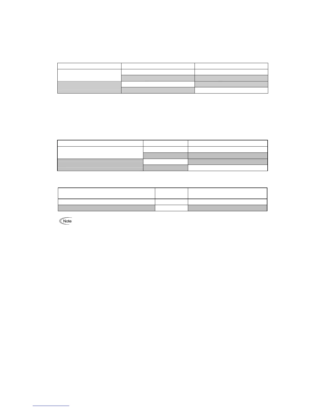
As listed below, the combination of the "Selection of normal/inverse operation for frequency command 1" (C53) and
the IVS terminal command determines the final operation.
Combination of C53 and
IVS
Data for C53
IVS Final operation
OFF Normal
0: Normal operation
ON Inverse
OFF Inverse
1: Inverse operation
ON Normal
• When the process control is performed by the PID processor integrated in the inverter:
The terminal command Hz/PID ("Cancel PID control") can switch the PID control between enabled (process is to be
controlled by the PID processor) and disabled (process is to be controlled by the manual frequency setting). In either
case, the combination of the "PID control" (J01) or "Selection of normal/inverse operation for frequency command 1"
(C53) and the terminal command
IVS determines the final operation as listed below.
When the PID control is enabled:
The normal/inverse operation selection for the PID processor output (reference frequency) is as follows.
PID control (Mode selection) (J01) IVS Final operation
OFF Normal
1: Enable (normal operation)
ON Inverse
OFF Inverse
2: Enable (inverse operation)
ON Normal
When the PID control is disabled:
The normal/inverse operation selection for the manual reference frequency is as follows.
Selection of normal/inverse operation for frequency
command 1 (C53)
IVS Final operation
0: Normal operation – Normal
1: Inverse operation – Inverse
When the process control is performed by the PID control facility integrated in the inverter, the IVS is use
any normal/inverse operation selection of the manual frequency setting.
Refer to the descriptions of J01 through J19 and J56 through J62.
■ Universal DI -- U-DI (Function code data = 25)
Using U-DI enables the inverter to monitor digital signals sent from the peripheral equipment via an RS-485
communications link or a fieldbus option by feeding those signals to the digital input terminals. Signals assigned to the
universal DI are simply monitored and do not operate the inverter.
For an access to universal DI via the RS-485 or fieldbus communications link, refer to their respective Instruction
Manuals.
■ Force to stop -- STOP (Function code data = 30)
Turning this terminal command OFF causes the motor to decelerate to a stop in accordance with the H56 data
(Deceleration time for forced stop). After the motor stops, the inverter enters the alarm state with the alarm
er6
displayed. (
Refer to the description of F07.)
■ Reset PID integral and differential components -- PID-RST (Function code data = 33)
Turning this terminal command ON resets the integral and differential components of the PID processor. ( Refer to
the descriptions of J01 through J19 and J56 through J62.)
■ Hold PID integral component -- PID-HLD (Function code data = 34)
Turning this terminal command ON holds the integral components of the PID processor. ( Refer to the descriptions
of J01 through J19 and J56 through J62.)