3-9
Chap. 3 OPERATION USING THE KEYPAD
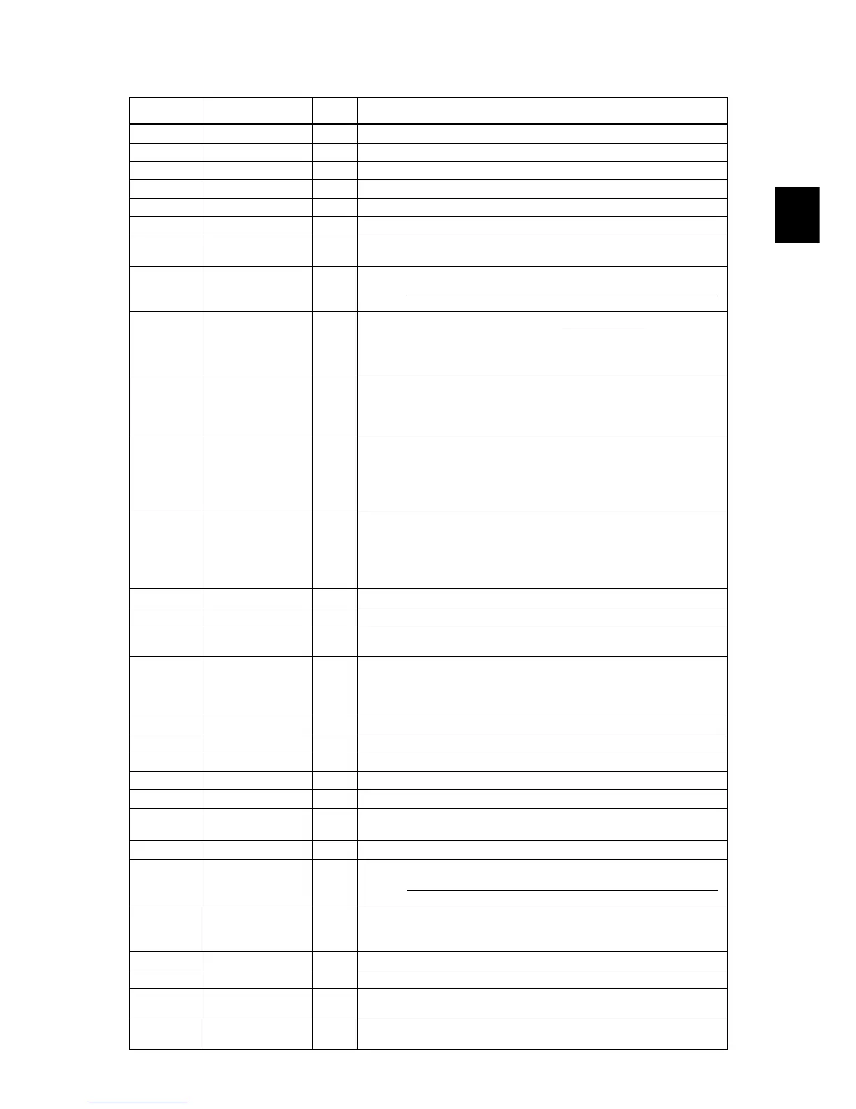
Table 3.6 "Drive Monitoring" Display Items
LED monitor
shows:
Item Unit Description
3_00
Output frequency Hz Output frequency before slip compensation
3_01
Output frequency Hz Output frequency after slip compensation
3_02
Output current A Output current
3_03
Output voltage V Output voltage
3_04
Calculated torque % Calculated output torque of the motor in %
3_05
Reference frequency Hz Frequency specified by a frequency command
3_06
Rotational direction N/A
Rotational direction being outputted
f
: forward,
r
: reverse,
----
: stop
3_07
Running status N/A
Running status in 4-digit hexadecimal format
Refer to "
Displaying running status (
3_07
) and running status 2 (
3_23
)"
on the next page.
120
Display value = (Output frequency Hz) ×
(No. of poles)
3_08
Motor speed r/min
If the value is 10000 or lager, the x10 LED turns ON and the LED monitor
shows one-tenth of the value.
3_09
Load shaft speed r/min
Display value = (Output frequency Hz)
× (Function code E50: Coefficient for
speed indication)
If the value is 10000 or lager, the x10 LED turns ON and the LED monitor
shows one-tenth of the value.
3_10
PID command value N/A
Virtual physical value (e.g., temperature or pressure) of the object to be
controlled, which is converted from the PID command value using function
code E40 and E41 data (PID display coefficients A and B)
Display value = (PID command value)
× (Coefficient A - B) + B
If PID control is disabled, "
----
" appears.
3_11
PID feedback
amount
N/A
Virtual physical value (e.g., temperature or pressure) of the object to be
controlled, which is converted from the PID feedback amount using function
code E40 and E41 data (PID display coefficients A and B)
Display value = (PID feedback amount)
× (Coefficient A - B) + B
If PID control is disabled, "
----
" appears.
3_12
Torque limit value % Driving torque limit value A (based on motor rated torque)
3_13
Torque limit value % Braking torque limit value B (based on motor rated torque)
3_14
Ratio setting %
When this setting is 100%, the LED monitor shows 1.00 time of the value to
be displayed. If no ratio setting is selected, "
----
" appears.
3_15
Line speed m/min
Display value = (Output frequency Hz)
× (Function code E50: Coefficient for
speed indication)
If the value is 10000 or lager, the x10 LED turns ON and the LED monitor
shows one-tenth of the value.
3_16
(Not used.) ― ―
3_17
(Not used.) ― ―
3_18
(Not used.) ― ―
3_19
(Not used.) ― ―
3_20
(Not used.) ― ―
3_21
PID output value %
PID output value in %. (100% at the maximum frequency)
If PID control is disabled, "
----
" appears.
3_22
Flux command value % Flux command value in %.
3_23
Running status 2 N/A
Running status 2 in 4-digit hexadecimal format
Refer to "
Displaying running status (
3_07
) and running status 2 (
3_23
)"
on the next page.
3_24
Motor temperature ºC
Temperature detected by the NTC thermistor built in the motor (Fuji VG
motor exclusively designed for vector control)
If the NTC thermistor connectivity is disabled, "
----
" appears.
3_25
(Not used.) ― ―
3_26
(Not used.) ― ―
3_27
Current position
pulse, 4-multiplied
pulse Current position pulse for positioning control (servo lock)
3_28
Position deviation
pulse, 4-multiplied
pulse Position deviation pulse for positioning control (servo lock)