5-16
Chap. 5 FUNCTION CODES
F codes
E codes
C codes
P codes
H codes
A codes
b codes
r codes
J codes
d codes
U codes
y codes
Drive control
Name Data setting range
Change when
running
Data copying
Default
setting
V/f
PG
V/f
w/o
PG
w/
PG
Torque
control
Refer
to
page:
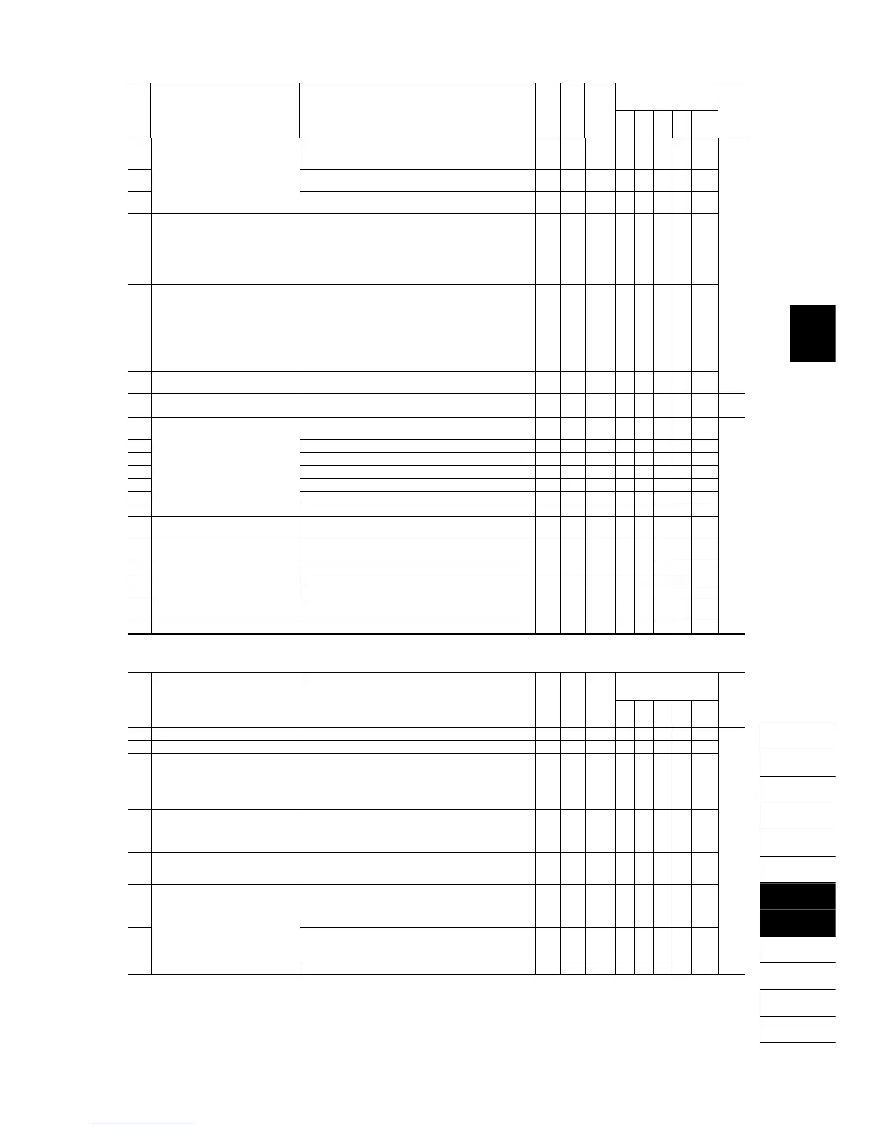
b35 Motor 3
(Magnetic saturation extension
factor "a")
0.0% to 300.0% Y Y1 Y2 *7 Y Y Y Y Y ―
b36 (Magnetic saturation extension
factor "b")
0.0% to 300.0% Y Y1 Y2 *7 Y Y Y Y Y
b37 (Magnetic saturation extension
factor "c")
0.0% to 300.0% Y Y1 Y2 *7 Y Y Y Y Y
b39 Motor 3 Selection 0: Motor characteristics 0 (Fuji standard motors, 8-series)
1: Motor characteristics 1 (HP rating motors)
2: Motor characteristics 2 (Fuji motors exclusively designed
for vector control)
3: Motor characteristics 3 (Fuji standard motors, 6-series)
4: Other motors
N Y1 Y2 0 Y Y Y Y Y
b40 Slip Compensation 3
(Operating conditions)
0: Enable during ACC/DEC and at base frequency or
above
1: Disable during ACC/DEC and enable at base frequency
or above
2: Enable during ACC/DEC and disable at base frequency
or above
3: Disable during ACC/DEC and at base frequency or
above
N Y 0 Y Y N N N
b41 Output Current Fluctuation Damping
Gain for Motor 3
0.00 to 0.40 Y Y 0.20 Y Y N N N
b42 Motor/Parameter Switching 3
(Mode selection)
0: Motor (Switch to the 3rd motor)
1: Parameter (Switch to particular b codes)
N Y 0 Y Y Y Y Y 5-117
b43 Speed Control 3
(Speed command filter)
0.000 to 5.000 s Y Y 0.020 N Y Y Y N ―
b44 (Speed detection filter) 0.000 to 0.100 s Y* Y 0.005 N Y Y Y N
b45 P (Gain) 0.1 to 200.0 times Y* Y 10.0 N Y Y Y N
b46 I (Integral time) 0.001 to 9.999 s Y* Y 0.100 N Y Y Y N
b48 (Output filter) 0.000 to 0.100 s Y Y 0.002 N Y Y Y N
b49 (Notch filter resonance frequency) 1 to 200 Hz Y Y 200 N N N Y N
b50 (Notch filter attenuation level) 0 to 20 dB Y Y 0 N N N Y N
b51 Cumulative Motor Run Time 3 0 to 9999 (The cumulative run time can be modified or reset
in units of 10 hours.)
N N - Y Y Y Y Y
b52 Startup Counter for Motor 3 Indication of cumulative startup count
0000 to FFFF (hex.)
Y N - Y Y Y Y Y
b53 Motor 3 (%X correction factor 1) 0% to 300% Y Y1 Y2 100 Y Y Y Y Y
b54 (%X correction factor 2) 0% to 300% Y Y1 Y2 100 Y Y Y Y Y
b55 (Torque current under vector control) 0.00 to 2000 A N Y1 Y2 *7 N N Y Y Y
b56 (Induced voltage factor under
vector control)
50 to 100 N Y1 Y2 85 N N Y Y Y
b57 Reserved *9 0.000 to 20.000 s Y Y1 Y2 *7 - - - - -
r codes: Motor 4 Parameters
Drive control
Code Name Data setting range
Change when
running
Data copying
Default
setting
V/f
PG
V/f
w/o
PG
w/
PG
Torque
control
Refer
to
page:
r01 Maximum Frequency 4 25.0 to 500.0 Hz N Y *1 Y Y Y Y Y ―
r02 Base Frequency 4 25.0 to 500.0 Hz N Y 50.0 Y Y Y Y Y
r03 Rated Voltage at Base Frequency 4 0: Output a voltage in proportion to input voltage
80 to 240: Output an AVR-controlled voltage
(for 200 V class series)
160 to 500: Output an AVR-controlled voltage
(for 400 V class series)
N Y2 *1 Y Y Y Y Y
r04 Maximum Output Voltage 4 80 to 240: Output an AVR-controlled voltage
(for 200 V class series)
160 to 500: Output an AVR-controlled voltage
(for 400 V class series)
N Y2 *1 Y Y N N Y
r05 Torque Boost 4 0.0% to 20.0%
(percentage with respect to "r03: Rated Voltage at Base
Frequency 4")
Y Y *3 Y Y N N N
r06 Electronic Thermal Overload
Protection for Motor 4
(Select motor characteristics)
1: For a general-purpose motor with shaft-driven cooling
fan
2: For an inverter-driven motor, non-ventilate*d motor, or
motor with separately powered cooling fan
Y Y 1 Y Y Y Y Y
r07 (Overload detection level) 0.00: Disable
1% to 135% of the rated current (allowable continuous drive
current) of the motor
Y Y1 Y2 *4 Y Y Y Y Y
r08 (Thermal time constant) 0.5 to 75.0 min Y Y *5 Y Y Y Y Y
*1 The factory default differs depending upon the shipping destination. See Table A.
*3 The factory default differs depending upon the inverter's capacity. See Table B.
*4 The motor rated current is automatically set. See Table C (function code P03).
*5 5.0 min for inverters with a capacity of 22 kW or below; 10.0 min for those with 30 kW or above
*7 The motor parameters are automatically set, depending upon the inverter's capacity and shipping destination. See Table C.
*9 These function codes are reserved for particular manufacturers. Unless otherwise specified, do not access these function codes.

 Loading...


