5-120
F codes
E codes
C codes
P codes
H codes
A codes
b codes
r codes
J codes
d codes
U codes
y codes
Chap. 5 FUNCTION CODES
5.2.7 J codes (Application Functions 1)
J01 PID Control (Mode selection)
Under PID control, the inverter detects the state of a control target object with a sensor or the similar device and
compares it with the commanded value (e.g., temperature control command). If there is any deviation between them, the
PID control operates so as to minimize it. That is, it is a closed loop feedback system that matches controlled variable
(feedback amount). The PID control expands the application area of the inverter to the process control (e.g., flow
control, pressure control, and temperature control) and the speed control (e.g., dancer control).
If PID control is enabled (J01 = 1, 2 or 3), the frequency control of the inverter is switched from the drive frequency
command generator block to the PID command generator block.
Data for J01 Function
0 Disable
1 Enable (Process control, normal operation)
2 Enable (Process control, inverse operation)
Mode Selection (J01)
J01 selects the PID control mode.
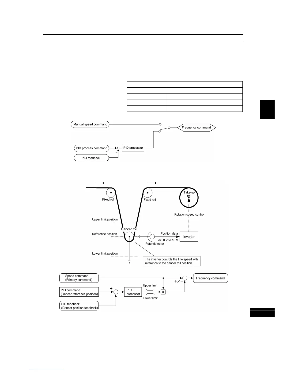
3 Enable (Dancer control)
PID process control block diagram
PID dancer control block diagram
Using J01 enables switching between normal and inverse operations against the PID control output, so you can specify
an increase/decrease of the motor rotating speed to the difference (error component) between the commanded (input)
and feedback amounts, making it possible to apply the inverter to air conditioners. The terminal command
IVS can also
switch operation between normal and inverse.
For details about the switching of normal/inverse operation, refer to the description of Switch normal/inverse
operation
IVS (E01 to E07, data = 21).

 Loading...


