5-64
F codes
E codes
C codes
P codes
H codes
A codes
b codes
r codes
J codes
d codes
U codes
y codes
Chap. 5 FUNCTION CODES
F43, F44 Current Limiter (Mode selection, Level) H12 (Instantaneous Overcurrent Limiting (Mode selection))
When the output current of the inverter exceeds the level specified by the current limiter (F44), the inverter
automatically manages its output frequency to prevent a stall and limit the output current.
The default setting is 160%, 145% and 130% for HD-, MD- and LD-mode inverters, respectively. (Once the HD, MD,
or LD mode is selected by F80, the current limit for each mode is automatically specified.)
If 160% (145% or 130%) or over of overcurrent instantaneously flows and the output frequency decreases by this
current limit that is undesired, consider increasing the current limit level.
If F43 = 1, the current limiter is enabled only during constant speed operation. If F43 = 2, the current limiter is enabled
during both of acceleration and constant speed operation. Choose F43 = 1 if you need to run the inverter at full
capability during acceleration and to limit the output current during constant speed operation.
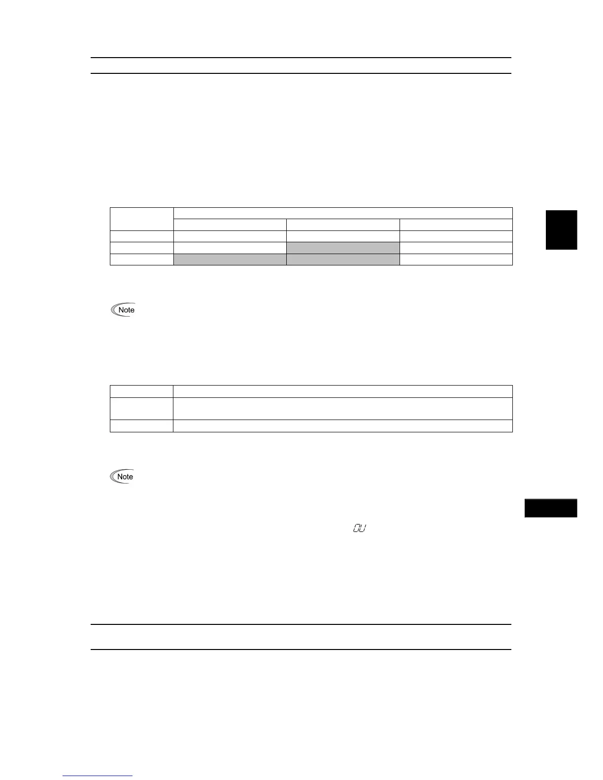
Mode selection (F43)
F43 selects the motor running state in which the current limiter will be active.
Running states that enable the current limiter
Data for F43
During acceleration During constant speed During deceleration
0 Disable Disable Disable
1 Disable Enable Disable
2 Enable Enable Disable
Level (F44) Data setting range: 20 to 200 (%) (in ratio to the inverter rating)
F44 specifies the operation level at which the output current limiter becomes activated, in ratio to the inverter rating.
The inverter's rated current differs depending upon the HD, MD, or LD mode selected.
Instantaneous Overcurrent Limiting (Mode selection) (H12)
H12 specifies whether the inverter invokes the current limit processing or enters the overcurrent trip when its output
current exceeds the instantaneous overcurrent limiting level. Under the current limit processing, the inverter
immediately turns OFF its output gate to suppress the further current increase and continues to control the output
frequency.
Data for H12 Function
0
Disable
An overcurrent trip occurs at the instantaneous overcurrent limiting level.
1 Enable
If any problem occurs in use of the equipment or machine is expected when the motor torque temporarily drops during
current limiting processing, it is necessary to cause an overcurrent trip (H12 = 0) and actuate a mechanical brake at the
same time.
• Since the current limit operation with F43 and F44 is performed by software, it may cause a delay in control.
If you need a quick response current limiting, also enable the instantaneous overcurrent limiting with H12.
• If an excessive load is applied when the current limiter operation level is set extremely low, the inverter will
rapidly lower its output frequency. This may cause an overvoltage trip or dangerous turnover of the moto
rotation due to undershooting. Depending on the load, extremely short acceleration time may activate the
current limiting to suppress the increase of the inverter output frequency, causing the system oscillation
(hunting) or activating the inverter overvoltage trip (alarm
0
u
). When specifying the acceleration time,
therefore, you need to take into account machinery characteristics and moment of inertia of the load.
• The torque limiter and current limiter are very similar function each other. If both are activated concurrently,
they may conflict each other and cause hunting in the system. Avoid concurrent activation of these limiters.
• The vector control itself contains the current control system, so it disables the current limiter specified by
F43 and F44, as well as automatically disabling the instantaneous overcurrent limiting (specified by H12).
Accordingly, the inverter causes an overcurrent trip when its output current exceeds the instantaneous
overcurrent limiting level.
F50 to F52 Electronic Thermal Overload Protection for Braking Resistor
(Discharging capability, Allowable average loss and Resistance)
These function codes specify the electronic thermal overload protection feature for the braking resistor.
Set the discharging capability, allowable average loss and resistance to F50, F51 and F52, respectively. These values
are determined by the inverter and braking resistor models. For the discharging capability, allowable average loss and
resistance, refer to FRENIC-MEGA User's Manual, Chapter 4 "SELECTING PERIPHERAL EQUIPMENT." The
values listed in the manual are for standard models and 10% ED models of the braking resistors which Fuji Electric
provides. If you use a braking resistor of other maker, confirm the corresponding values with the maker, and set the
function codes accordingly.