5-37
Examples:
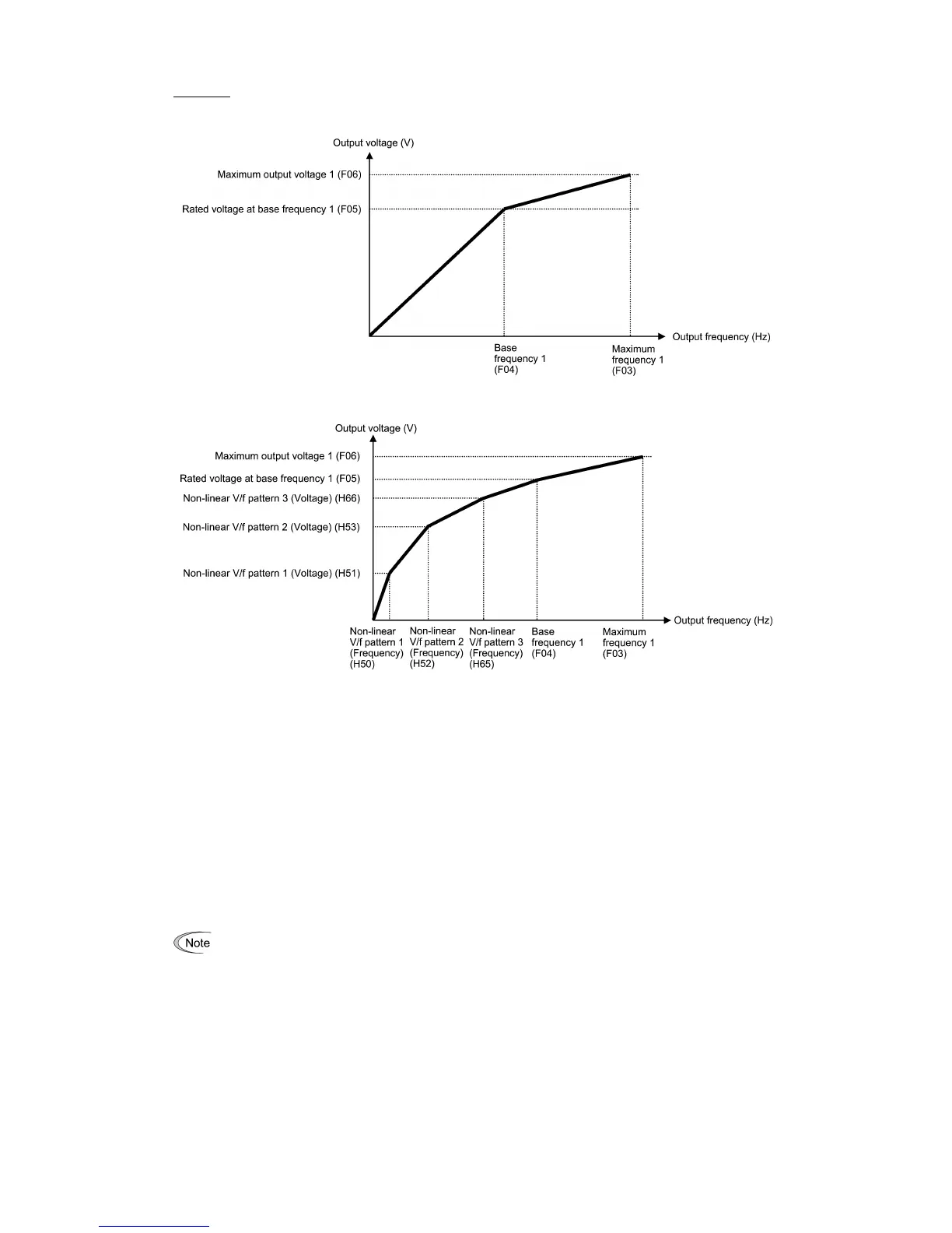
Normal (linear) V/f pattern
V/f pattern with three non-linear points
Base Frequency 1 (F04) Data setting range: 25.0 to 500.0 (Hz)
Set the rated frequency printed on the nameplate labeled on the motor.
Rated Voltage at Base Frequency 1 (F05)
Data setting range: 0: Output a voltage in proportion to input voltage
(The Automatic Voltage Regulator (AVR) is disabled.)
80 to 240 (V): Output an AVR-controlled voltage for 200 V class series
160 to 500 (V): Output an AVR-controlled voltage for 400 V class series
Set "0" or the rated voltage printed on the nameplate labeled on the motor.
- If F05 = 0, the rated voltage at base frequency is determined by the power source of the inverter. The output voltage
will fluctuate in line with the input voltage fluctuation.
- If F05 = an arbitrary value other than 0, the inverter automatically keeps the output voltage constant in line with the
setting. When any of the auto torque boost, auto energy saving, etc. is enabled, the F05 data should be equal to the
rated voltage of the motor.
In vector control, current feedback control is performed. In the current feedback control, the current is
controlled with the difference between the motor induced voltage and the inverter output voltage. For a prope
control, the inverter output voltage should be sufficiently higher than the motor induced voltage. Generally,
the voltage difference is about 20 V for 200 V class series, about 40 V for 400 V class series.
The voltage the inverter can output is at the same level as the inverter input voltage. Configure these voltages
correctly in accordance with the motor specifications.
When a Fuji VG motor (exclusively designed for vector control) is used, configuring the inverter for using a
VG motor with P02 (Rated capacity) and P99 (Motor 1 Selection) automatically configures F04 (Base
Frequency 1) and F05 (Rated Voltage at Base Frequency 1).
When enabling the vector control without speed sensor using a general-
Voltage at Base Frequency 1) data at the rated voltage of the motor. The voltage difference described above is
specified by function code P56 (Induced voltage factor under vector control). Generally, there is no need to
modify the initial setting.

 Loading...


