2-16
Chap. 2 MOUNTING AND WIRING THE INVERTER
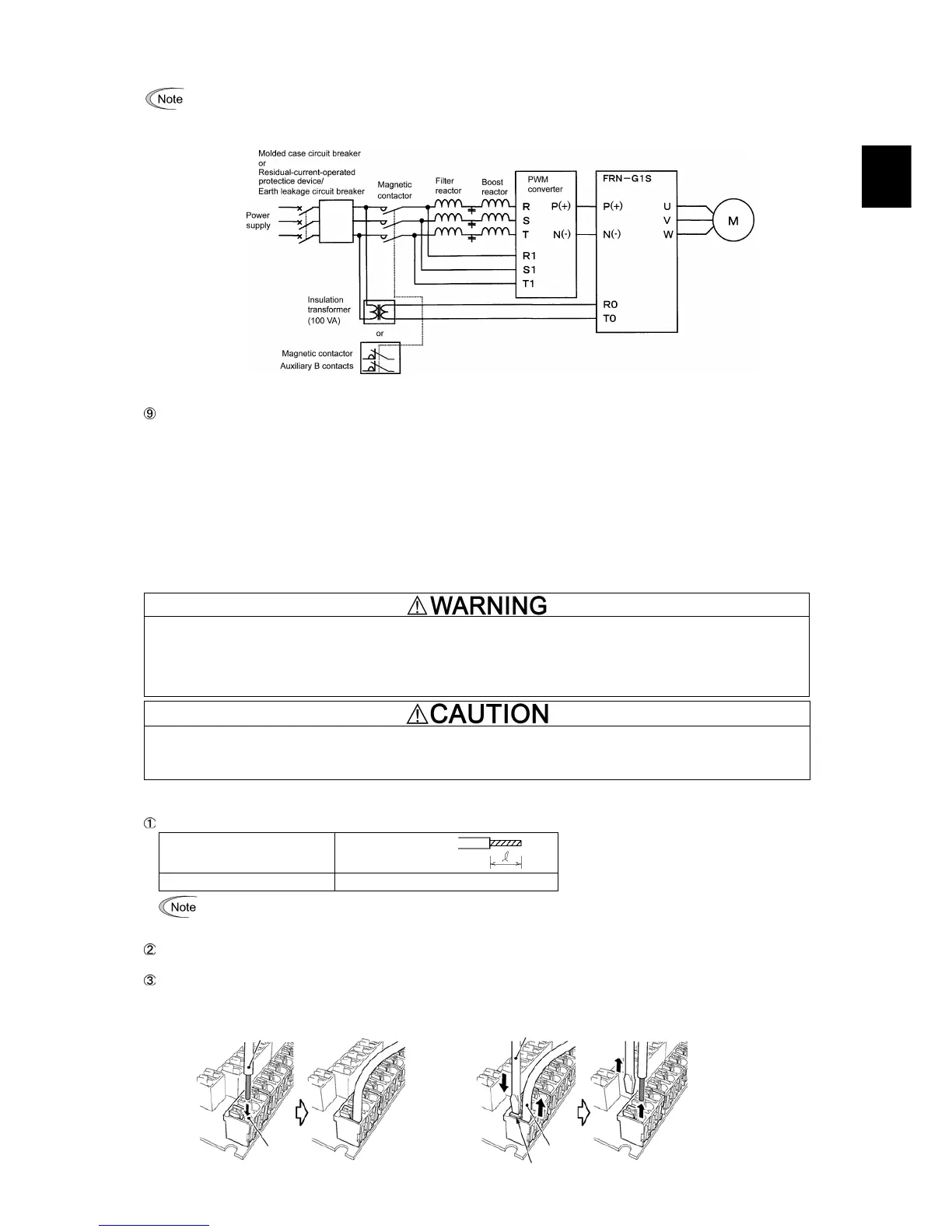
When connecting a PWM converter with an inverter, do not connect the power supply line directly to terminals R0
and T0. If a PWM is to be connected, insert an insulation transformer or auxiliary B contacts of a magnetic
contactor at the power supply side.
For connection examples at the PWM converter side, refer to the PWM Converter Instruction Manual.
Figure 2.9 Connection Example of PWM Converter
Auxiliary fan power input terminals R1 and T1
The 200 V class series with 37 kW or above and 400 V class series with 75 kW or above are equipped with terminals R1 and
T1. Only if the inverter works with the DC-linked power input whose source is a PWM converter, these terminals are used to
feed AC power to the fans, while they are not used in any power system of ordinary configuration.
In this case, set up the fan power supply switching connectors (CN R and CN W).
Terminal rating:
200 to 220 VAC/50 Hz, 200 to 230 VAC/60 Hz, Maximum current 1.0 A (200 V class series with 37 kW or above)
380 to 440 VAC/50 Hz, 380 to 480 VAC/60 Hz, Maximum current 1.0 A (400 V class series with 75 kW to 400 kW)
380 to 440 VAC/50 Hz, 380 to 480 VAC/60 Hz, Maximum current 2.0 A (400 V class series with 500 kW and 630 kW)
2.3.5 Wiring for control circuit terminals
In general, the covers of the control signal wires are not specifically designed to withstand a high voltage (i.e., reinforced
insulation is not applied). Therefore, if a control signal wire comes into direct contact with a live conductor of the main
circuit, the insulation of the cover might break down, which would expose the signal wire to a high voltage of the main
circuit. Make sure that the control signal wires will not come into contact with live conductors of the main circuit.
Failure to observe these precautions could cause electric shock or an accident.
Noise may be emitted from the inverter, motor and wires.
Take appropriate measures to prevent the nearby sensors and devices from malfunctioning due to such noise.
An accident could occur.
Connecting/disconnecting wires to/from a control circuit terminal
Strip the wire end by 8 to 10 mm as shown below.
Strip length of wire end 8 to 10 mm
Type of screwdriver (tip shape) Flat (0.6 × 3.5 mm)
For strand wires, the strip length specified above should apply after twisting of them.
If the strip length is out of the specified range, the wire may not be firmly clamped or may be short-circuited wit
other wires.
Twist the end of the stripped wires for easy insertion and insert it firmly into the wire inlet on the control circuit terminal.
If the insertion is difficult, hold down the clamp release button on the terminal with a flat screwdriver.
When disconnecting the wires from the terminal, hold down the clamp release button on the terminal with a flat
screwdriver and pull out the wires.
Connecting wire to terminal Disconnecting wire from terminal
Wires
Flat screwdrive