3-3
Chap. 3 OPERATION USING THE KEYPAD
3.3 Running Mode
3.3.1 Monitoring the running status
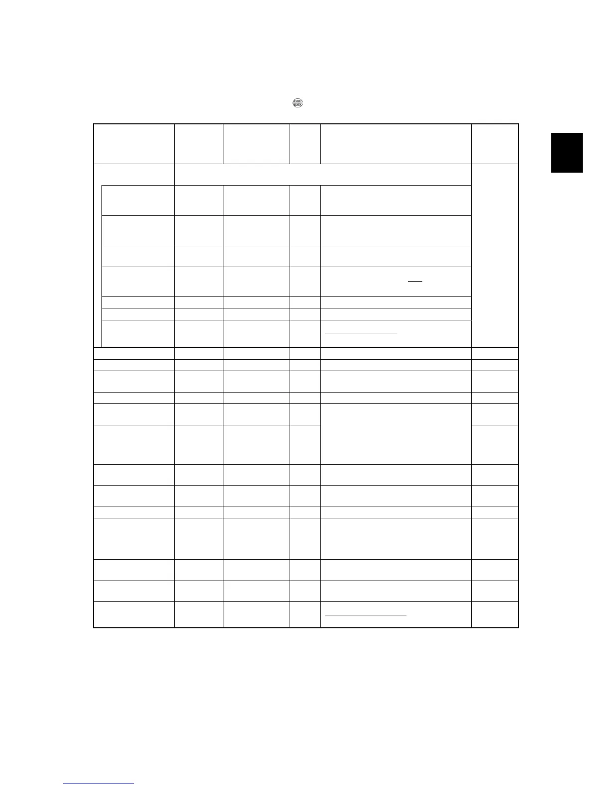
In Running mode, the fourteen items listed below can be monitored. Immediately after the inverter is turned ON, the monitor
item specified by function code E43 is displayed. Press the
key to switch between these monitor items.
Table 3.3 Monitoring Items
Monitor items
Display
sample on the
LED monitor
*
1
LED indicator
: ON, : OFF
Unit Meaning of displayed value
Function
code data
for E43
Speed monitor
Function code E48 specifies what to be displayed on the LED monitor and LED
indicators.
0
Output frequency 1
(before slip
compensation)
5*00
Hz A kW Hz Frequency actually being output (E48 = 0)
Output frequency 2
(after slip
compensation)
5*00
Hz A kW Hz Frequency actually being output (E48 = 1)
Reference
frequency
5*00
Hz A kW Hz Reference frequency being set (E48 = 2)
Motor speed
1500
Hz A kW r/min
P01
120
× (Hz)frequency Output
(E48 = 3)
Load shaft speed
30*0
Hz A kW r/min Output frequency (Hz) × E50 (E48 = 4)
Line speed
30*0
Hz A kW m/min Output frequency (Hz) × E50 (E48 = 5)
Speed (%)
5*0
Hz A kW %
100x
frequency Maximum
frequencyOutput
(E48 = 7)
Output current
1"34
Hz A kW A Current output from the inverter in RMS 3
Output voltage *
2
200u
Hz A kW V Voltage output from the inverter in RMS 4
Calculated torque
50
Hz A kW %
Motor output torque in %
(Calculated value)
8
Input power
1*25
Hz A kW kW Input power to the inverter 9
PID command
*
3
, *
4
1*0*
Hz A kW ― 10
PID feedback amount
*
3
, *
5
)0*
Hz A kW ―
PID command/feedback amount
transformed to that of virtual physical
value of the object to be controlled (e.g.
temperature)
Refer to function codes E40 and E41 for
details.
12
PID output *
3
, *
4
10**
Hz A kW %
PID output in % as the maximum
frequency (F03) being at 100%
14
Load factor *
6
50;
Hz A kW %
Load factor of the motor in % as the rated
output being at 100%
15
Motor output *
7
)85
Hz A kW % Motor output in kW 16
Analog input monitor
*
8
8"00
Hz A kW ―
An analog input to the inverter in a format
suitable for a desired scale.
Refer to function codes E40 and E41 for
details.
17
Torque current *
9
48
Hz A kW %
Torque current command value or
calculated torque current
23
Magnetic flux
command
*9
50
Hz A kW % Magnetic flux command value 24
Input watt-hour
10*0
Hz A kW kWh
100
(kWh)hour -Input watt
25
*1 A value exceeding 9999 cannot be displayed as is on the 4-digit LED monitor screen, so the LED monitor displays one-tenth of the actual
value with the x10 LED lit.
*2 When the LED monitor displays an output voltage, the 7-segment letter u in the lowest digit stands for the unit of the voltage "V."
*3 These PID related items appear only when the inverter drives the motor under the PID control specified by function code J01 (= 1, 2 or 3).
*4 When the LED monitor displays a PID command or its output amount, the dot (decimal point) attached to the lowest digit of the 7-segment
letter blinks.
*5 When the LED monitor displays a PID feedback amount, the dot (decimal point) attached to the lowest digit of the 7-segment letter lights.
*6 When the LED monitor displays a load factor, the 7-segment letter ; in the lowest digit stands for "%."
*7 When the LED monitor displays the motor output, the unit LED indicator "kW" blinks.
*8 The analog input monitor can appear only when the analog input monitor function is assigned to any of the analog input terminals by any of
function codes E61 to E63 (= 20).
*9
0
appears under the V/f control.

 Loading...


