5-80
F codes
E codes
C codes
P codes
H codes
A codes
b codes
r codes
J codes
d codes
U codes
y codes
Chap. 5 FUNCTION CODES
Inverter output limiting -- IOL (Function code data = 5)
Inverter output limiting with delay --
IOL2 (Function code data = 22)
The output signal IOL comes ON when the inverter is limiting the output frequency by activating any of the following
actions (minimum width of the output signal: 100 ms). The output signal
IOL2 comes ON when any of the following
output limiting operation continues for 20 ms or more.
• Torque limiting (F40, F41, E16 and E17, Maximum internal value)
• Current limiting by software (F43 and F44)
• Instantaneous overcurrent limiting by hardware (H12 = 1)
• Automatic deceleration (Anti-regenerative control) (H69)
When the IOL signal is ON, it may mean that the output frequency may have deviated from the frequency
specified by the frequency command because of this limiting function.
Keypad operation enabled -- KP (Function code data = 8)
This output signal comes ON when the / keys are specified as the run command source.
■ Inverter ready to run -- RDY (Function code data = 10)
This output signal comes ON when the inverter becomes ready to run by completing hardware preparation (such as
initial charging of DC link bus capacitors and initialization of the control circuit) and no protective functions are
activated.
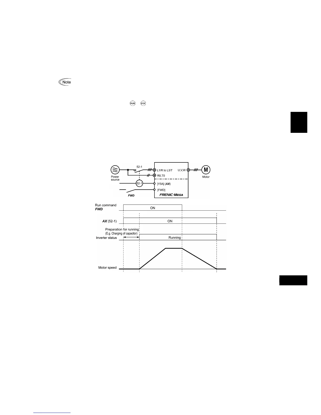
Select AX terminal function -- AX (Function code data = 15)
In response to a run command FWD, this output signal controls the magnetic contactor on the commercial-power
supply side. It comes ON when the inverter receives a run command and it goes OFF after the motor decelerates to stop
with a stop command received.
This signal immediately goes OFF upon receipt of a coast-to-stop command or when an alarm occurs.
Universal DO -- U-DO (Function code data = 27)
Assigning this output signal to an inverter's output terminal and connecting the terminal to a digital input terminal of
peripheral equipment via the RS-485 communications link or the fieldbus, allows the inverter to send commands to the
peripheral equipment.
The universal DO can also be used as an output signal independent of the inverter operation.
For the procedure for access to Universal DO via the RS-485 communications link or fieldbus, refer to the
respective instruction manual.
Heat sink overheat early warning -- OH (Function code data = 28)
This output signal is used to issue a heat sink overheat early warning that enables you to take a corrective action before
an overheat trip
0h1
actually happens.
This signal comes ON when the temperature of the heat sink exceeds the "overheat trip temperature minus 5°C," and it
goes OFF when it drops down to the "overheat trip temperature minus 8°C."
This signal comes ON also when the internal air circulation DC fan (45 kW or above for 200 V class series or 75 kW or
above for 400 V class series) has locked.
Lifetime alarm -- LIFE (Function code data = 30)
This output signal comes ON when it is judged that the service life of any one of capacitors (DC link bus capacitors and
electrolytic capacitors on the printed circuit boards) and cooling fan has expired.
This signal should be used as a guide for replacement of the capacitors and cooling fan. If this signal comes ON, use the
specified maintenance procedure to check the service life of these parts and determine whether the parts should be
replaced or not. (Refer to Chapter 7, Section 7.3 "List of Periodic Replacement Parts.")
This signal comes ON also when the internal air circulation DC fan (45 kW or above for 200 V class series or 75 kW or
above for 400 V class series) has locked.

 Loading...


