5-33
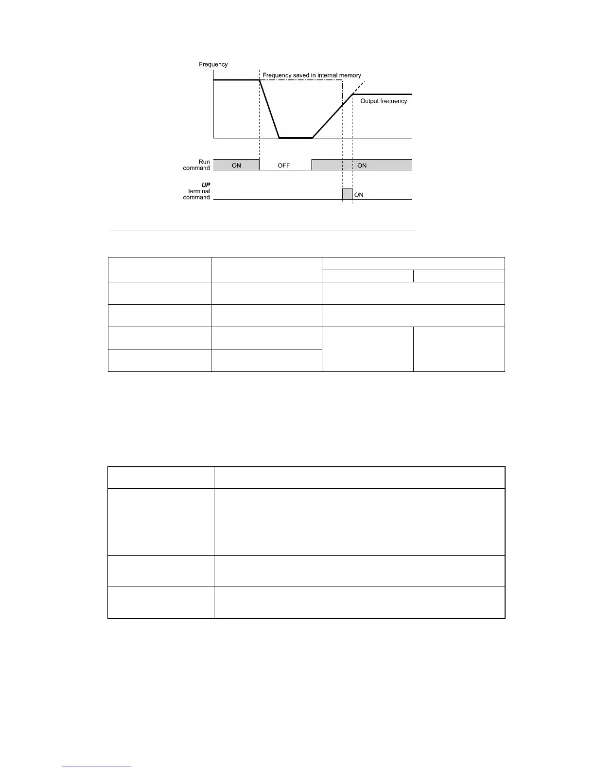
Initial frequency for the UP/DOWN control when the frequency command source is switched
When the frequency command source is switched to the UP/DOWN control from other sources, the initial frequency for
the UP/DOWN control is as listed below:
Initial frequency for UP/DOWN control
Frequency command source Switching command
H61 = 0 H61 = 1
Other than UP/DOWN
(F01, C30)
Select frequency
command 2/1 (Hz2/Hz1)
Reference frequency given by the frequency
command source used just before switching
PID control Cancel PID control (Hz/PID)
Reference frequency given by PID control (PID
controller output)
Multi-frequency
Select multi-frequency
(SS1, SS2, SS4 and SS8)
Communications link
Enable communications link
via RS-485 or fieldbus (LE)
Reference frequency
given by the frequency
command source used
just before switching
Reference frequency at
the time of previous
UP/DOWN control
[ 4 ] Using pulse train input (F01 = 12)
Selecting the pulse train input format (d59)
A pulse train in the format selected by the function code d59 can give a frequency command to the inverter. Three types
of formats are available; the pulse train sign/pulse train input, the forward rotation pulse/reverse rotation pulse, and the
A and B phases with 90 degree phase difference. If no optional PG interface card is mounted, the inverter ignores the
setting of the function code d59 and accepts only the pulse train sign/pulse train input.
The table below lists pulse train formats and their operations.
Pulse train input format
selected by d59
Operation overview
0: Pulse train sign/
Pulse train input
Frequency/speed command according to the pulse train rate is given to the inverter.
The pulse train sign specifies the polarity of the frequency/speed command.
• For the inverter without an optional PG interface card
Pulse train input: PIN assigned to the digital terminal [X7] (data = 48)
Pulse train sign: SIGN assigned to a digital terminal other than [X7] (data = 49)
If no SIGN is assigned, polarity of any pulse train input is positive.
1: Forward rotation
pulse/Reverse rotation
pulse
Frequency/speed command according to the pulse train rate is given to the inverter.
The forward rotation pulse gives a frequency/speed command with positive
polarity, and a reverse rotation pulse, with negative polarity.
2: A and B phases with 90
degree phase difference
Pulse trains generated by A and B phases with 90 degree phase difference give a
frequency/speed command based on their pulse rate and the phase difference to an
inverter.
For details of operations using the optional PG interface card, refer to the Instruction Manual for it.

 Loading...


