1-4
Chap. 1
BEFORE USING THE INVERTER
Wiring precautions
(1) Route the wiring of the control circuit terminals as far from the wiring of the main circuit as possible. Otherwise electric
noise may cause malfunctions.
(2) Fix the control circuit wires inside the inverter to keep them away from the live parts of the main circuit (such as the
terminal block of the main circuit).
(3) If more than one motor is to be connected to a single inverter, the wiring length should be the sum of the length of the
wires to the motors.
(4) Precautions for high frequency leakage currents
If the wiring distance between an inverter and a motor is long, high frequency currents flowing through stray capacitance
across wires of phases may cause an inverter overheat, overcurrent trip, increase of leakage current, or it may not assure
the accuracy in measuring leakage current. Depending on the operating condition, an excessive leakage current may
damage the inverter.
To avoid the above problems when directly connecting an inverter to a motor, keep the wiring distance 50 m or less for
inverters with a capacity of 3.7 kW or below, and 100 m or less for inverters with a higher capacity.
If the wiring distance longer than the specified above is required, lower the carrier frequency or insert an output circuit
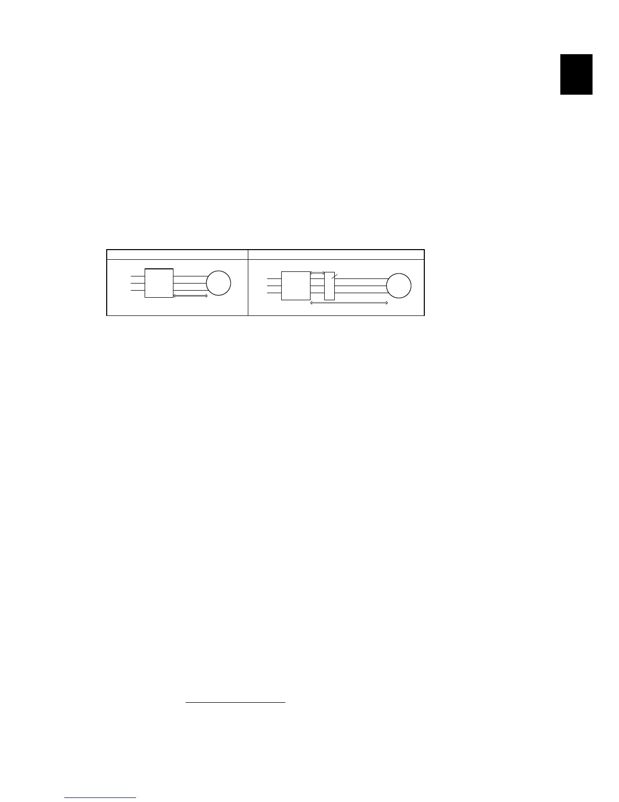
filter (OFL--A) as shown below.
When the inverter drives two or more motors connected in parallel (group drive), in particular, using shielded wires, the
stray capacitance to the earth is large, so lower the carrier frequency or insert an output circuit filter (OFL--A).
No output circuit filter installed Output circuit filter installed
MotorInverter
Power
input
Max. 50 m
Max. 100 m
Inverter Motor
Max. 5 m
Max. 400 m
Output circuit filter
Power
input
For an inverter with an output circuit filter installed, the total secondary wiring length should be 400 m or less (100 m or
less under the vector control).
If further longer secondary wiring is required, consult your Fuji Electric representative.
(5) Precautions for surge voltage in driving a motor by an inverter (especially for 400 V class, general-purpose motors)
If the motor is driven by a PWM-type inverter, surge voltage generated by switching the inverter component may be
superimposed on the output voltage and may be applied to the motor terminals. Particularly if the wiring length is long,
the surge voltage may deteriorate the insulation resistance of the motor. Implement any of the following measures.
- Use a motor with insulation that withstands the surge voltage. (All Fuji standard motors feature reinforced insulation.)
- Connect a surge suppressor unit (SSU50/100TA-NS) at the motor terminal.
- Connect an output circuit filter (OFL--A) to the output terminals (secondary circuits) of the inverter.
- Minimize the wiring length between the inverter and motor (10 to 20 m or less).
(6) When an output circuit filter is inserted in the secondary circuit or the wiring between the inverter and the motor is long,
a voltage loss occurs due to reactance of the filter or wiring so that the insufficient voltage may cause output current
oscillation or a lack of motor output torque. To avoid it, select the constant torque load by setting the function code F37
(Load Selection/Auto Torque Boost/Auto Energy Saving Operation 1) to "1" and keep the inverter output voltage at a
higher level by configuring H50/H52 (Non-linear V/f Pattern, Frequency) and H51/H53 (Non-linear V/f Pattern,
Voltage).
Precautions for connection of peripheral equipment
(1) Phase-advancing capacitors for power factor correction
Do not mount a phase-advancing capacitor for power factor correction in the inverter's input (primary) or output
(secondary) circuit. Mounting it in the input (primary) circuit takes no effect. To correct the inverter power factor, use an
optional DC reactor (DCR). Mounting it in the output (secondary) circuit causes an overcurrent trip, disabling operation.
An overvoltage trip that occurs when the inverter is stopped or running with a light load is assumed to be due to surge
current generated by open/close of phase-advancing capacitors in the power system. An optional DC/AC reactor
(DCR/ACR) is recommended as a measure to be taken at the inverter side.
Input current to an inverter contains a harmonic component that may affect other motors and phase-advancing capacitors
on the same power supply line. If the harmonic component causes any problems, connect an optional DCR/ACR to the
inverter. In some cases, it is necessary to insert a reactor in series with the phase-advancing capacitors.
(2) Power supply lines (Application of a DC/AC reactor)
Use an optional DC reactor (DCR) when the capacity of the power supply transformer is 500 kVA or more and is 10
times or more the inverter rated capacity or when there are thyristor-driven loads. If no DCR is used, the
percentage-reactance of the power supply decreases, and harmonic components and their peak levels increase. These
factors may break rectifiers or capacitors in the converter section of the inverter, or decrease the capacitance of the
capacitors.
If the input voltage unbalance rate is 2% to 3%, use an optional AC reactor (ACR).
3)61800 (IEC 67×
(V) voltage average phase-Three
(V)voltage Min - (V) voltageMax
(%) unbalance Voltage
= -
(3) DC reactor (DCR) for correcting the inverter input power factor (for suppressing harmonics)
To correct the inverter input power factor (to suppress harmonics), use an optional DCR. Using a DCR increases the
reactance of inverter’s power source so as to decrease harmonic components on the power source lines and correct the
power factor of the inverter.