2-4
Chap. 2 MOUNTING AND WIRING THE INVERTER
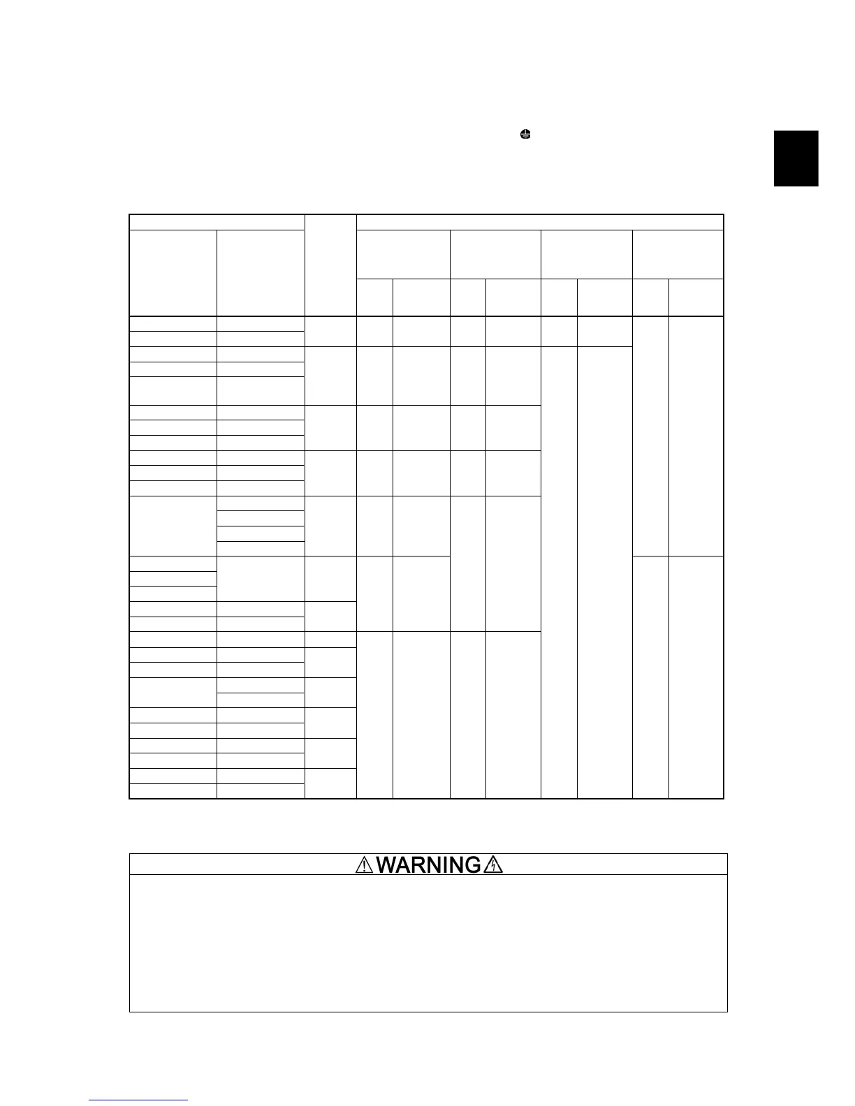
2.3.2 Screw specifications and recommended wire sizes
(1) Arrangement of main circuit terminals
The tables and figures given below show the screw specifications and wire sizes. Note that the terminal arrangements differ
depending on the inverter types. In each of the figures, two grounding terminals (
G) are not exclusive to the power supply
wiring (primary circuit) or motor wiring (secondary circuit).
Use crimp terminals covered with an insulation sheath or with an insulation tube. The recommended wire sizes for the main
circuits are examples of using a single HIV wire (JIS C3317) (for 75°C) at a surrounding temperature of 50°C.
Table 2.5 Screw Specifications
Inverter type Screw specifications
Main circuit
terminals
Grounding terminals
Auxiliary control
power input
terminals
[R0, T0]
Auxiliary fan
power input
terminals
[R1, T1]
Three-phase
200 V
Three-phase
400 V
Refer to:
Screw
size
Tightening
torque
(N·m)
Screw
size
Tightening
torque
(N·m)
Screw
size
Tightening
torque
(N·m)
Screw
size
Tightening
torque
(N·m)
FRN0.4G1
-2 FRN0.4G1
-4
FRN0.75G1
-2 FRN0.75G1
-4
Figure A
M3.5 1.2 M3.5 1.2 -- --
FRN1.5G1
-2 FRN1.5G1
-4
FRN2.2G1
-2 FRN2.2G1
-4
FRN3.7G1
-2
FRN3.7G1
-4A
FRN4.0G1
-4E*
Figure B
M4 1.8 M4 1.8
FRN5.5G1
-2 FRN5.5G1
-4
FRN7.5G1
-2 FRN7.5G1
-4
FRN11G1
-2 FRN11G1
-4
Figure C
M5 3.5 M5 3.5
FRN15G1
-2 FRN15G1
-4
FRN18.5G1
-2 FRN18.5G1
-4
FRN22G1
-2 FRN22G1
-4
Figure D
M6 5.8 M6 5.8
FRN30G1
-4
FRN37G1
-4
FRN45G1
-4
FRN30G1
-2
FRN55G1
-4
Figure E
M8 13.5
-- --
FRN37G1
-2
FRN45G1
-2
FRN55G1
-2
FRN75G1
-4
Figure F
-- FRN90G1
-4
-- FRN110G1
-4
Figure G
M10 27
M8 13.5
FRN75G1
-2 --
Figure M
-- FRN132G1
-4
-- FRN160G1
-4
Figure H
FRN200G1
-4
FRN90G1
-2
FRN220G1
-4
Figure I
-- FRN280G1
-4
-- FRN315G1
-4
Figure J
-- FRN355G1
-4
-- FRN400G1
-4
Figure K
-- FRN500G1
-4
-- FRN630G1
-4
Figure L
M12 48 M10 27
M3.5 1.2
M3.5 1.2
* 4.0 kW for the EU. The inverter type is FRN4.0G1
-4E.
Note: A box (
) in the above table replaces S or E depending on the enclosure.
A box () in the above table replaces A or E depending on the shipping destination.
When the inverter power is ON, a high voltage is applied to the following terminals.
Main circuit terminals: L1/R, L2/S, L3/T, P1, P(+), N(-), DB, U, V, W, R0, T0, R1, T1, AUX-contact (30A, 30B, 30C,
Y5A, Y5C)
Insulation level
Main circuit ― Enclosure : Basic insulation (Overvoltage category III, Pollution degree 2)
Main circuit ― Control circuit : Reinforced insulation (Overvoltage category III, Pollution degree 2)
Relay output ― Control circuit : Reinforced insulation (Overvoltage category II, Pollution degree 2)
An electric shock may occur.