5-38
F codes
E codes
C codes
P codes
H codes
A codes
b codes
r codes
J codes
d codes
U codes
y codes
Chap. 5 FUNCTION CODES
Non-linear V/f Patterns 1, 2 and 3 for Frequency (H50, H52 and H65)
Data setting range: 0.0 (cancel); 0.1 to 500.0 (Hz)
Set the frequency component at an arbitrary point in the non-linear V/f pattern.
Setting "0.0" to H50, H52 or H65 disables the non-linear V/f pattern operation.
Non-linear V/f Patterns 1, 2 and 3 for Voltage (H51, H53 and H66)
Data setting range: 0 to 240 (V): Output an AVR-controlled voltage for 200 V class series
0 to 500 (V): Output an AVR-controlled voltage for 400 V class series
Sets the voltage component at an arbitrary point in the non-linear V/f pattern.
The factory default values for H50 and H51 differ depending on the inverter capacity.
For inverters with a capacity of 22 kW or below, H50 = 0.0 (Hz) and H51 = 0 (V). For those with a capacity o
30 kW or above, refer to the table below.
Destination Asia EU
Inverter type FRN_ _ _G1
-2A FRN_ _ _G1
-4A FRN_ _ _G1
-4E
Voltage 200 V class series 400 V class series 400 V class series
H50 6.0 (Hz) 5.0 (Hz) 5.0 (Hz)
H51 22 (V) 42 (V) 40 (V)
Note: A box (
) in the above table replaces S or E depending on the enclosure.
Maximum Output Voltage 1 (F06)
Data setting range: 80 to 240 (V): Output an AVR-controlled voltage for 200 V class series
160 to 500 (V): Output an AVR-controlled voltage for 400 V class series
Set the voltage for the maximum frequency 1 (F03).
If F05 (Rated Voltage at Base Frequency 1) is set to "0," settings of H50 through H53, H65, H66 and F06 do
not take effect. (When the non-linear point is below the base frequency, the linear V/f pattern applies; when i
is above, the output voltage is kept constant.)
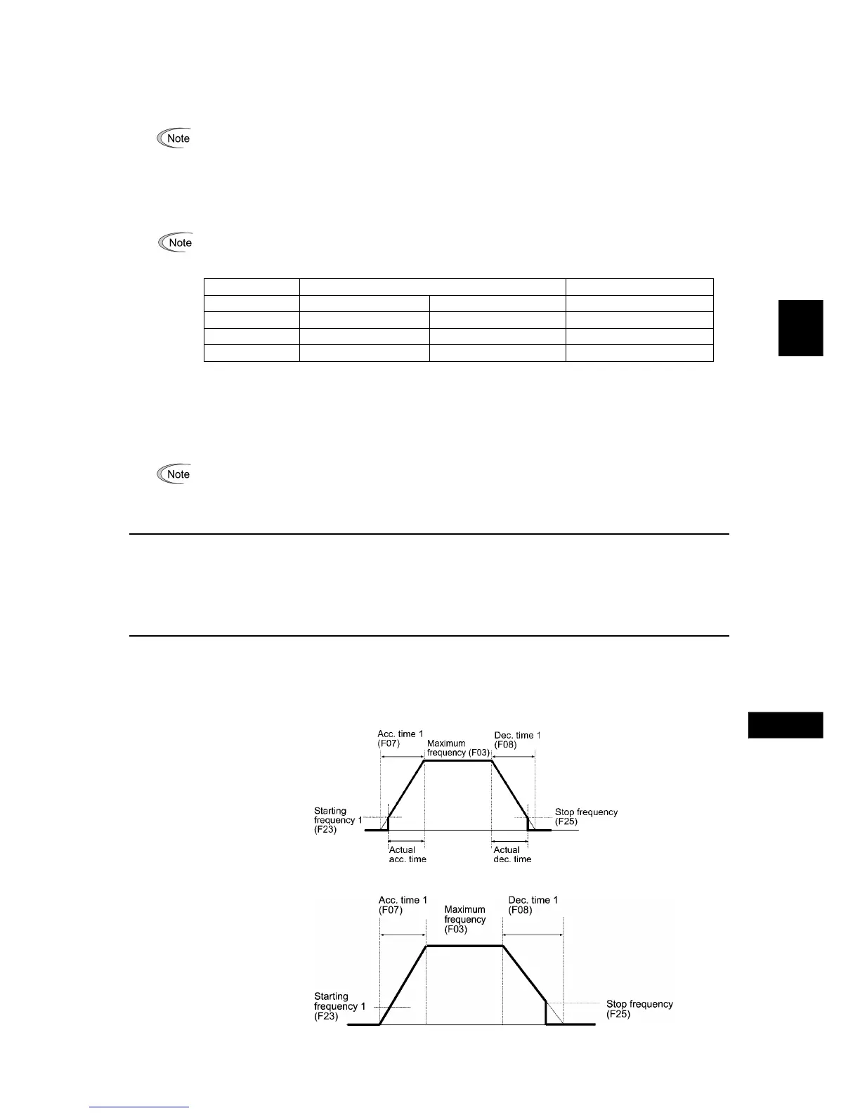
F07, F08 Acceleration Time 1, Deceleration Time 1
E10, E12, E14 (Acceleration Time 2, 3 and 4)
E11, E13, E15 (Deceleration Time 2, 3 and 4)
H07 (Acceleration/Deceleration Pattern)
H56 (Deceleration Time for Forced Stop)
H54, H55 (Acceleration Time/Deceleration Time, Jogging)
H57 to H60 (1st and 2nd S-curve Acceleration/Deceleration Range)
F07 specifies the acceleration time, the length of time the frequency increases from 0 Hz to the maximum frequency.
F08 specifies the deceleration time, the length of time the frequency decreases from the maximum frequency down to 0
Hz.
- Data setting range: 0.00 to 6000 (s)
Under V/f control
Under vector control without speed sensor
CTi Automation - Phone: 800.894.0412 - Fax: 208.368.0415 - Web: www.ctiautomation.net - Email: info@ctiautomation.net

 Loading...


