5-94
F codes
E codes
C codes
P codes
H codes
A codes
b codes
r codes
J codes
d codes
U codes
y codes
Chap. 5 FUNCTION CODES
■ Starting jogging operation
Pressing the
key or turning the
FWD or REV terminal command ON starts jogging.
In jogging with the
key, the inverter jogs only when the
key is held down. Releasing the
key decelerates
to stop.
To start jogging operation by simultaneously entering the
JOG terminal command and a run command (e.g.,
FWD), the input delay time between the two commands should be within 100 ms. If a run command FWD is
entered first, the inverter does not jog the motor but runs it ordinarily until the next input of the
JOG.
The jogging conditions should be specified beforehand using the following function codes.
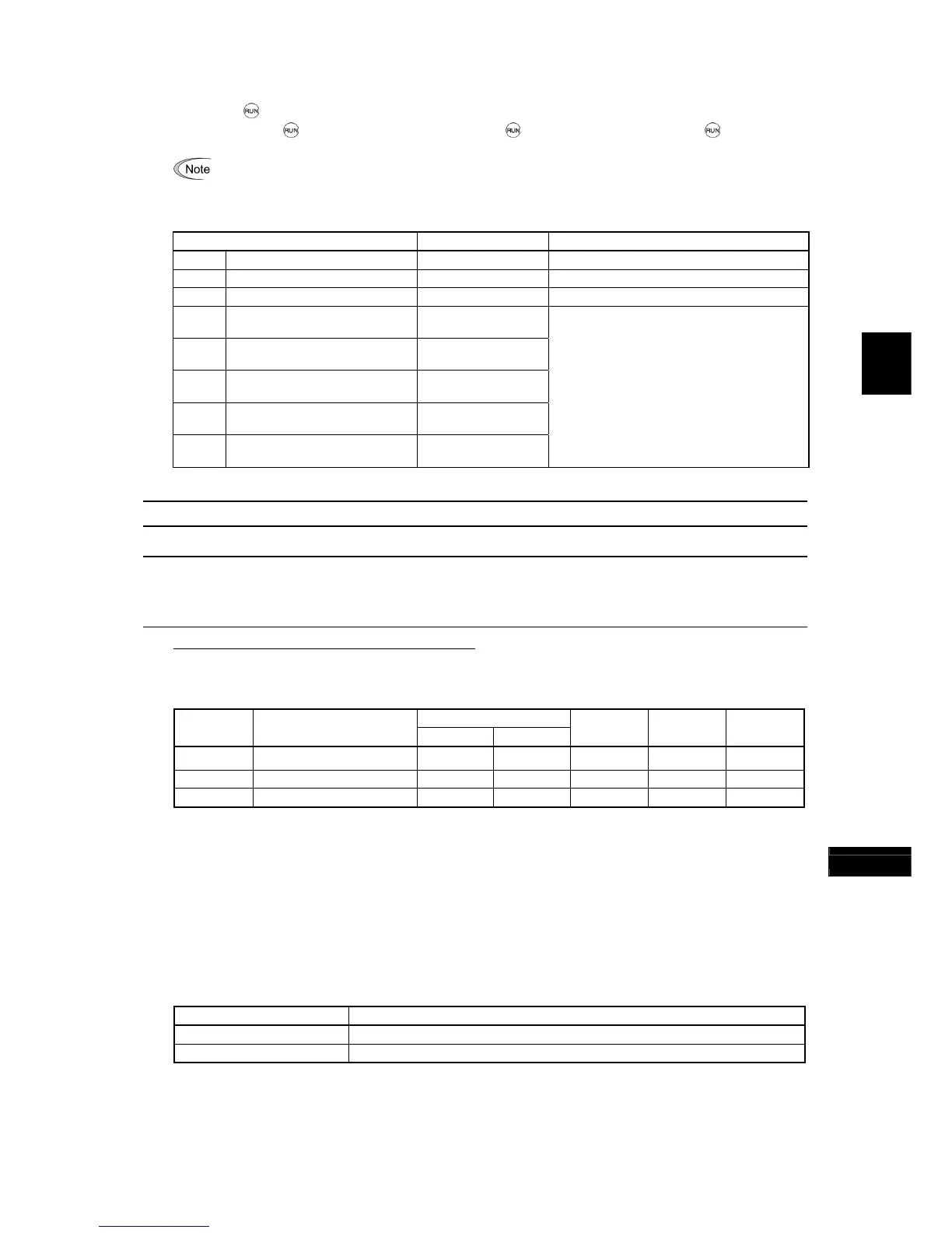
Function code Data setting range Description
C20 Jogging Frequency 0.00 to 500.00 Hz Reference frequency for jogging operation
H54 Acceleration Time (Jogging) 0.00 to 6000 s Acceleration time for jogging operation
H55 Deceleration Time (Jogging) 0.00 to 6000 s Deceleration time for jogging operation
d09
Speed Control (Jogging)
(Speed command filter)
0.000 to 5.000 s
d10
Speed Control (Jogging)
(Speed detection filter)
0.000 to 0.100 s
d11
Speed Control (Jogging)
P (Gain)
0.1 to 200.0 times
d12
Speed Control (Jogging)
I (Integral time)
0.001 to 9.999 s
d13
Speed Control (Jogging)
(Output filter)
0.000 to 0.100 s
Modification items related to speed control
for jogging operation under vector control
without/with speed sensor
For adjustments, refer to the descriptions of
d01 to d06.
C30 Frequency Command 2 (Refer to F01.)
C31 to C35
C36 to C39
C41 to C45
Analog Input Adjustment for [12] (Offset, Gain, Filter time constant, Gain base point, Polarity)
Analog Input Adjustment for [C1] (Offset, Gain, Filter time constant, Gain base point)
Analog Input Adjustment for [V2] (Offset, Gain, Filter time constant, Gain base point, Polarity)
(For details about the frequency command, refer to F01 (Frequency Command 1).)
Setting up a reference frequency using analog input
You can adjust the gain, polarity, filter time constant, and offset which are applied to analog inputs (voltage inputs to
terminals [12] and [V2], and current input to terminal [C1])
Adjustable items for analog inputs
Gain
Input
terminal
Input range
Gain Base point
Polarity
Filter time
constant
Offset
[12] 0 to +10 V, -10 to +10 V C32 C34 C35 C33 C31
[C1] 4 to 20 mA C37 C39 C38 C36
[V2] 0 to +10 V, -10 to +10 V C42 C44 C45 C43 C41
Offset (C31, C36, C41) Data setting range: -5.0 to +5.0 (%)
C31, C36 or C41 configures an offset for an analog voltage/current input. The offset also applies to signals sent from
the external equipment.
Filter time constant (C33, C38, C43) Data setting range: 0.00 to 5.00 (s)
C33, C38 or C43 configures a filter time constant for an analog voltage/current input. The larger the time constant, the
slower the response. Specify the proper filter time constant taking into account the response speed of the machine (load).
If the input voltage fluctuates due to line noises, increase the time constant.
Polarity (C35, C45)
C35 and C45 configure the input range for analog input voltage.
Data for C35 and C45 Specifications for terminal inputs
0 -10 to +10 V
1 0 to +10 V (A minus component of the input will be regarded as 0 VDC.)

 Loading...


