5-131
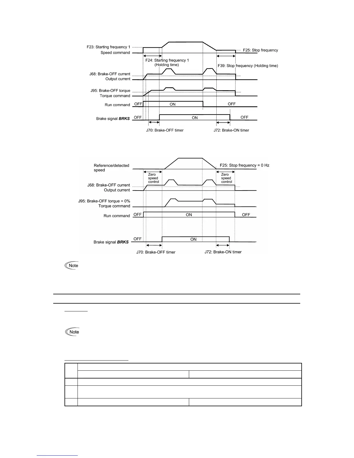
Operation time chart under vector control without speed sensor
Operation time chart under vector control with speed sensor
• If the zero speed control is enabled under vector control, set J95 (Brake-OFF torque) at 0%.
• After releasing the brake (
BRKS ON), operating for a while, and then activating the brake (BRKS OFF) to
stop the motor, if you want to release the brake (
BRKS ON), turn the inverter's run command OFF and then
ON.
J97 to J99 Servo-lock (Gain, Completion timer, Completion width)
Servo-lock
This function servo-locks the inverter to hold the motor within the positioning completion range specified by J99 for the
period specified by J98 even if an external force applies to the load.
When the inverter is servo-locked, it keeps the output frequency low; therefore, use the inverter under the
following specified thermal restriction: Output current within the range of 150% of the rated current for 3
seconds and 80% for continuous operation. (Note that under the restriction, the inverter automatically limits
the carrier frequency under 5 kHz.)
Servo-lock starting conditions
Servo-lock control starts when the following conditions are met:
F38 = 0 (Use detected speed as a decision criteria) F38 = 1 (Use reference speed as a decision criteria)
1 Run command OFF, or Reference frequency < Stop frequency (F25)
2
LOCK ("Servo-lock command") ON
(Assignment of
LOCK (Function code data = 47))
3 The detected speed is less than stop frequency (F25). The reference speed is less than stop frequency (F25).

 Loading...


