5-135
d14 to d17 Feedback Input (Pulse input format, Encoder pulse resolution,
Pulse count factor 1 and Pulse count factor 2)
These function codes specify the speed feedback input under vector control with speed sensor.
Feedback Input, Pulse input format (d14)
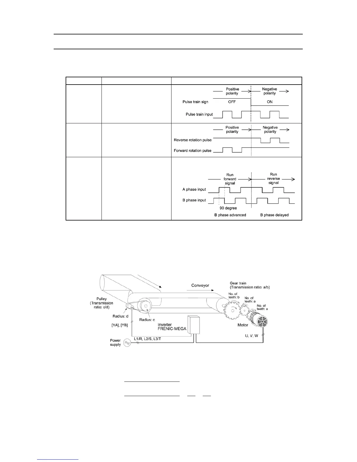
d14 specifies the speed feedback input format.
Data for d14 Pulse input mode Remarks
0 Pulse train sign/Pulse train input
1
Forward rotation pulse/
Reverse rotation pulse
2
A and B phases with 90 degree
phase difference
Set the d14 data to "2" for Fuji motors exclusively designed
for vector control.
Feedback Input, Encoder pulse resolution (d15) Data setting range: 0014 to EA60 (in hex.)
d15 specifies the pulse resolution (P/R) of the speed feedback encoder. (20 to 60000 P/R in decimal.)
For Fuji motors exclusively designed for vector control, set d15 at "0400 (1024 P/R)."
Feedback Input, Pulse count factor 1 (d16) and Pulse count factor 2 (d17) Data setting range: 1 to 9999
d16 and d17 specify the factors to convert the speed feedback input pulse rate into the motor shaft speed (r/min).
Specify the data according to the transmission ratios of the pulley and gear train as shown below.
An Example of a Closed Loop Speed Control System (Conveyor)
Listed below are expressions for conversion between a speed feedback input pulse rate and motor shaft speed.
Pulse count factor 2 (d17)
Motor shaft speed =
Pulse count factor 1 (d16)
× Encoder shaft speed
Pulse count factor 2 (d17) b d
Pulse count factor 1 (d16)
=
a
×
c
Pulse count factor 1 (d16)
=a
×
c
Pulse count factor 2 (d17) = b
×
d

 Loading...


