5-137
d32, d33 Torque Control (Speed limit 1 and Speed limit 2) (Refer to H18.)
d41 Application-Defined Control
The constant peripheral speed control is available as an application, which suppresses an increase in peripheral speed
(line speed) resulting from the increasing radius of the take-up roll in a winder system.
In a winder system (e.g., roving frames, wiredrawing machines), if the inverter continues to run the motor at a constant
speed, the take-up roll gets bigger with materials (roving, wire, etc.) and its radius increases so that the winding speed
of the take-up roll increases.
Under the application-defined control, to keep the peripheral speed (winding speed) constant, the inverter detects the
winding speed using an encoder and controls the motor rotation according to the encoder feedback.
Application-Defined Control (d41)
d41 specifies whether to enable or disable the constant peripheral speed control.
Data for d41 Function
0
Disable (Ordinary control)
1
Enable (Constant peripheral speed control)
Note: This control is valid only when "V/f control with speed sensor" or "Dynamic torque vector
control with speed sensor" is selected with F42, A14, b14, or r14 (data = 3 or 4).
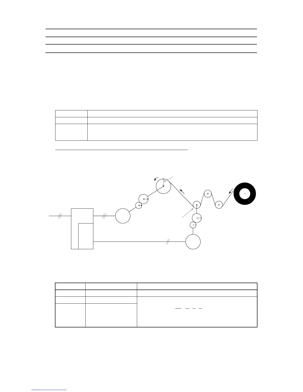
Mechanical configuration of a winder system and function code settings
Shown below is a typical mechanical configuration of a winder system for which it is necessary to configure the
function codes as listed below.
Inverter
Encoder
I/F card
U, V, W
R, S, T
Reduction ratio a:b
(When the motor shaft
rotates “b” times, the take-
up roll shaft rotates “a”
times.)
Speed v
in winding direction
Drum
Winder
(The radius of the take-up roll increases
as the roll rotates.)
Speed v
A/B phase or B phase
Motor
Encoder
b
a
c
d
Reduction ratio c: d
(When the speed detector shaft
rotates “d” times, the encoder
shaft rotates “c” times.)
Radius of take-up roll (r1)
Speed detector
radius r
2
- Speed reduction ratio between motor shaft and take-up roll shaft a : b
- Speed reduction ratio between speed detector shaft and encoder shaft c : d
- Radius of take-up roll before winding r
1
(m)
- Radius of speed detector r
2
(m)
Setting the Reduction Ratio
Function code Name Settings
d15
Encoder pulse resolution
Encoder pulse resolution (P/R) to be set in hexadecimal
d16
Pulse count factor 1
d17 Pulse count factor 2
Speed reduction ratio of the whole machinery (load)
d17/d16
c
d
a
b
r
r
K
K
1
2
1
2
=××=
d16: Denominator factor for the speed reduction ratio (K1 = r1 × a × c)
d17: Numerator factor for the speed reduction ratio (K2 = r2 × b × d)

 Loading...


