2-21
Table 2.7 Symbols, Names and Functions of the Control Circuit Terminals (Continued)
Classifi-
cation
Symbol Name Functions
[Y1]
Transistor
output 1
[Y2]
Transistor
output 2
(1) Various signals such as inverter running, speed/freq. arrival and overload early
warning can be assigned to any terminals, [Y1] to [Y4] by setting function code E20
to E24. Refer to Chapter 5, Section 5.2 "Details of Function Codes" for details.
(2) Switches the logic value (1/0) for ON/OFF of the terminals between [Y1] to [Y4],
and [CMY]. If the logic value for ON between [Y1] to [Y4] and [CMY] is 1 in the
normal logic system, for example, OFF is 1 in the negative logic system and vice
versa.
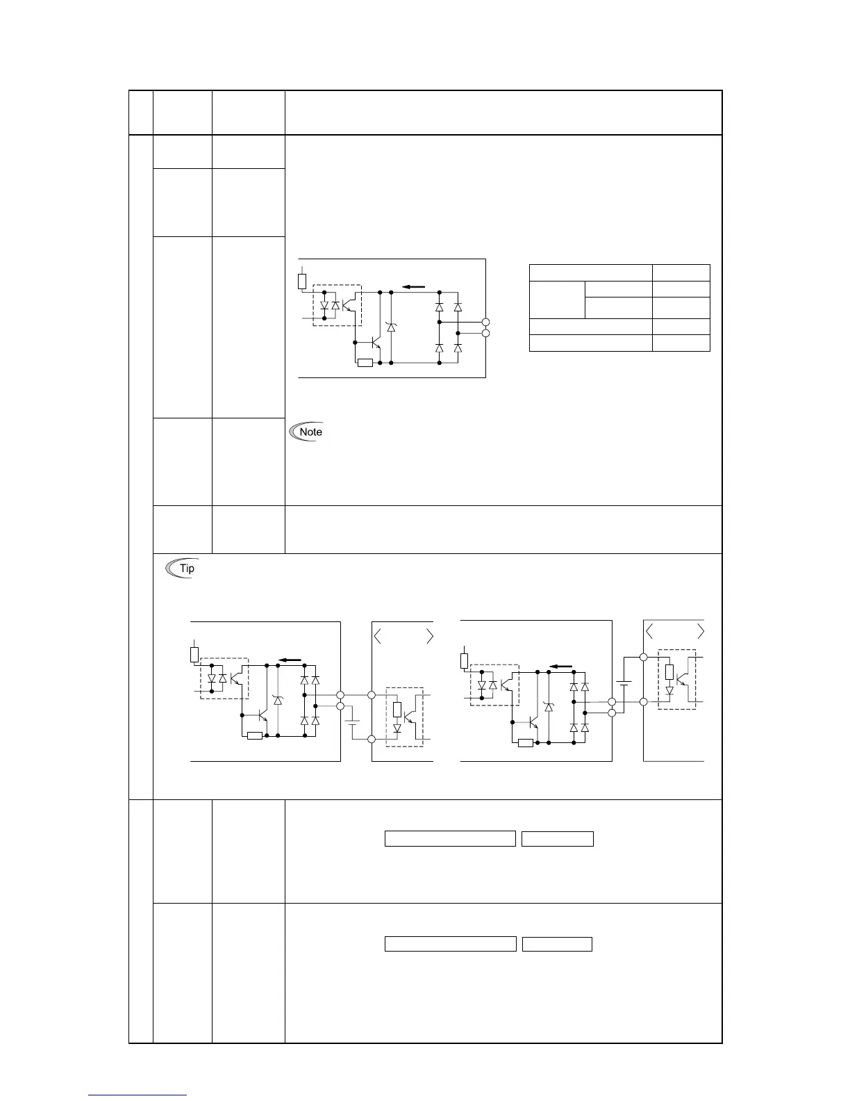
(Transistor output circuit specification)
Photocoupler
<Control circuit>
[Y1]
to
[Y4]
[CMY]
31 to 35 V
Voltage
Current
Figure 2.16 Transistor Output Circuit
Item Max.
ON level 2 V
Operation
voltage
OFF level 27 V
Maximum current at ON 50 mA
Leakage current at OFF 0.1 mA
[Y3]
Transistor
output 3
Figure 2.17 shows examples of connection between the control circuit and a PLC.
[Y4]
Transistor
output 4
- When a transistor output drives a control relay, connect a surge-absorbing diode
across relay’s coil terminals.
- When any equipment or device connected to the transistor output needs to be
supplied with DC power, feed the power (+24 VDC: allowable range: +22 to
+27 VDC, 100 mA max.) through the [PLC] terminal. Short-circuit between the
terminals [CMY] and [CM] in this case.
[CMY]
Transistor
output
common
Common terminal for transistor output signals
This terminal is electrically isolated from terminals [CM] and [11]s.
Connecting programmable logic controller (PLC) to terminal [Y1], [Y2], [Y3] or [Y4]
Figure 2.17 shows two examples of circuit connection between the transistor output of the inverter’s
control circuit and a PLC. In example (a), the input circuit of the PLC serves as a SINK for the control
circuit output, whereas in example (b), it serves as a SOURCE for the output.
C0
+24 VDC
Programmable
logic controller
SINK input
Photocoupler
<Control circuit>
[Y1]
to
[Y4]
[CMY]
31 to
35 V
Current
C0
Programmable
logic controller
SOURCE input
+24 VDC
Photocoupler
<Control circuit>
[Y1]
to
[Y4]
[CMY]
31 to
35 V
Current
(a) PLC serving as SINK (b) PLC serving as SOURCE
Transistor output
Figure 2.17 Connecting PLC to Control Circuit
[Y5A/C]
General
purpose relay
output
(1) A general-purpose relay contact output usable as well as the function of the transistor
output terminal [Y1], [Y2], [Y3] or [Y4].
Contact rating: 250 VAC 0.3 A, cos φ = 0.3, 48 VDC, 0.5 A
(2) Switching of the normal/negative logic output is applicable to the following two
contact output modes: "Active ON" (Terminals [Y5A] and [Y5C] are closed
(excited) if the signal is active.) and "Active OFF" (Terminals [Y5A] and [Y5C] are
opened (non-excited) if the signal is active while they are normally closed.).
Relay output
[30A/B/C]
Alarm relay
output
(for any
error)
(1) Outputs a contact signal (SPDT) when a protective function has been activated to
stop the motor.
Contact rating: 250 VAC, 0.3A, cos φ = 0.3, 48 VDC, 0.5A
(2) Any one of output signals assigned to terminals [Y1] to [Y4] can also be assigned to
this relay contact to use it for signal output.
(3) Switching of the normal/negative logic output is applicable to the following two
contact output modes: "Active ON" (Terminals [30A] and [30C] are closed (excited)
if the signal is active.) and "Active OFF" (Terminals [30A] and [30C] are opened
(non-excited) if the signal is active while they are normally closed.).