5-6
Chap. 5 FUNCTION CODES
F codes
E codes
C codes
P codes
H codes
A codes
b codes
r codes
J codes
d codes
U codes
y codes
Drive control
Code Name Data setting range
Change when
running
Data copying
Default
setting
V/f
PG
V/f
w/o
PG
w/
PG
Torque
control
Refer to
page:
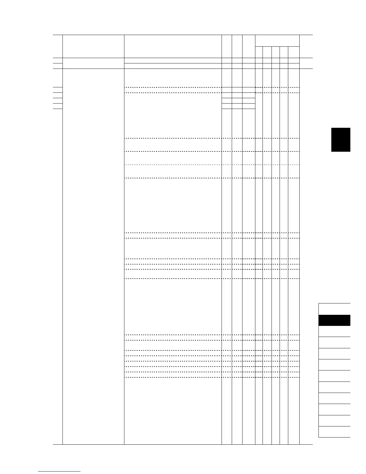
E16 Torque Limiter 2-1 -300% to 300%; 999 (Disable) Y Y 999 Y Y Y Y Y 5-57
E17 Torque Limiter 2-2 -300% to 300%; 999 (Disable) Y Y 999 Y Y Y Y Y 5-77
Selecting function code data assigns the corresponding
function to terminals [Y1] to [Y5A/C] and [30A/B/C] as
listed below.
E20 Terminal [Y1] Function 0 (1000): Inverter running (RUN) N Y 0 Y Y Y Y Y
E21 Terminal [Y2] Function 1 (1001): Frequency (speed) arrival signal (FAR) N Y 1 Y Y Y Y N
E22 Terminal [Y3] Function 2 (1002): Frequency (speed) detected (FDT) N Y 2 Y Y Y Y Y
E23 Terminal [Y4] Function 3 (1003): Undervoltage detected (Inverter stopped) (LU) N Y 7 Y Y Y Y Y
E24 Terminal [Y5A/C] Function N Y 15 Y Y Y Y Y
E27 Terminal [30A/B/C] Function
4 (1004): Torque polarity detected (B/D)
5 (1005): Inverter output limiting (IOL)
N Y 99 Y Y Y Y Y
5-77
(Relay output) 6 (1006): Auto-restarting after momentary power
failure (IPF)
Y
Y
Y
Y
Y
7 (1007): Motor overload early warning (OL) Y Y Y Y Y
8 (1008): Keypad operation enabled (KP) Y Y Y Y Y
10 (1010): Inverter ready to run (RDY) Y Y Y Y Y
11: Switch motor drive source between
commercial power and inverter output
(For MC on commercial line) (SW88)
Y
Y
N
N
N
12: Switch motor drive source between
commercial power and inverter output
(For secondary side) (SW52-2)
Y
Y
N
N
N
13: Switch motor drive source between
commercial power and inverter output
(For primary side) (SW52-1)
Y
Y
N
N
N
15 (1015): Select AX terminal function
(For MC on primary side) (AX)
Y
Y
Y
Y
Y
22 (1022): Inverter output limiting with delay (IOL2) Y Y Y Y Y
25 (1025): Cooling fan in operation (FAN) Y Y Y Y Y
26 (1026): Auto-resetting (TRY) Y Y Y Y Y
27 (1027): Universal DO (U-DO) Y Y Y Y Y
28 (1028): Heat sink overheat early warning (OH) Y Y Y Y Y
30 (1030): Lifetime alarm (LIFE) Y Y Y Y Y
31 (1031): Frequency (speed) detected 2 (FDT2) Y Y Y Y Y
33 (1033): Reference loss detected (REF OFF) Y Y Y Y Y
35 (1035): Inverter output on (RUN2) Y Y Y Y Y
36 (1036): Overload prevention control (OLP) Y Y Y Y N
37 (1037): Current detected (ID)
Y Y Y Y Y
38 (1038): Current detected 2 (ID2) Y Y Y Y Y
39 (1039): Current detected 3 (ID3) Y Y Y Y Y
41 (1041): Low current detected (IDL) Y Y Y Y Y
42 (1042): PID alarm (PID-ALM) Y Y Y Y N
43 (1043): Under PID control (PID-CTL) Y Y Y Y N
44 (1044): Motor stopped due to slow
flowrate under PID control (PID-STP)
Y
Y
Y
Y
N
45 (1045): Low output torque detected (U-TL)
Y Y Y Y Y
46 (1046): Torque detected 1 (TD1) Y Y Y Y Y
47 (1047): Torque detected 2 (TD2) Y Y Y Y Y
48 (1048): Motor 1 selected (SWM1) Y Y Y Y Y
49 (1049): Motor 2 selected (SWM2) Y Y Y Y Y
50 (1050): Motor 3 selected (SWM3) Y Y Y Y Y
51 (1051): Motor 4 selected (SWM4) Y Y Y Y Y
52 (1052): Running forward (FRUN) Y Y Y Y Y
53 (1053): Running reverse (RRUN) Y Y Y Y Y
54 (1054): In remote operation (RMT) Y Y Y Y Y
56 (1056): Motor overheat detected by thermistor (THM) Y Y Y Y Y
57 (1057): Brake signal (BRKS) Y Y Y Y N
58 (1058): Frequency (speed) detected 3 (FDT3)
Y Y Y Y Y
59 (1059): Terminal [C1] wire break (C1OFF) Y Y Y Y Y
70 (1070): Speed valid (DNZS) N Y Y Y Y
71 (1071): Speed agreement (DSAG) N Y Y Y N
72 (1072): Frequency (speed) arrival signal 3 (FAR3) Y Y Y Y N
76 (1076): PG error detected (PG-ERR) N Y Y Y N
82 (1082): Positioning completion signal (PSET) N N N Y N
84 (1084): Maintenance timer (MNT)
Y Y Y Y Y
98 (1098): Light alarm (L-ALM) Y Y Y Y Y
99 (1099): Alarm output (for any alarm) (ALM) Y Y Y Y Y
101 (1101): Enable circuit failure detected (DECF) Y Y Y Y Y
102 (1102): Enable input OFF (EN OFF) Y Y Y Y Y
105 (1105): Braking transistor broken (DBAL) Y Y Y Y Y
111 (1111): Customizable logic output signal 1 (CLO1) Y Y Y Y Y
112 (1112): Customizable logic output signal 2 (CLO2) Y Y Y Y Y
113 (1113): Customizable logic output signal 3 (CLO3) Y Y Y Y Y
114 (1114): Customizable logic output signal 4 (CLO4) Y Y Y Y Y
115 (1115): Customizable logic output signal 5 (CLO5) Y Y Y Y Y
Setting the value in parentheses ( ) shown above assigns
a negative logic output to a terminal.
 Loading...


