6.2 PG Interface Expansion Card
6-29
Chap. 6
CONTROL OPTIONS
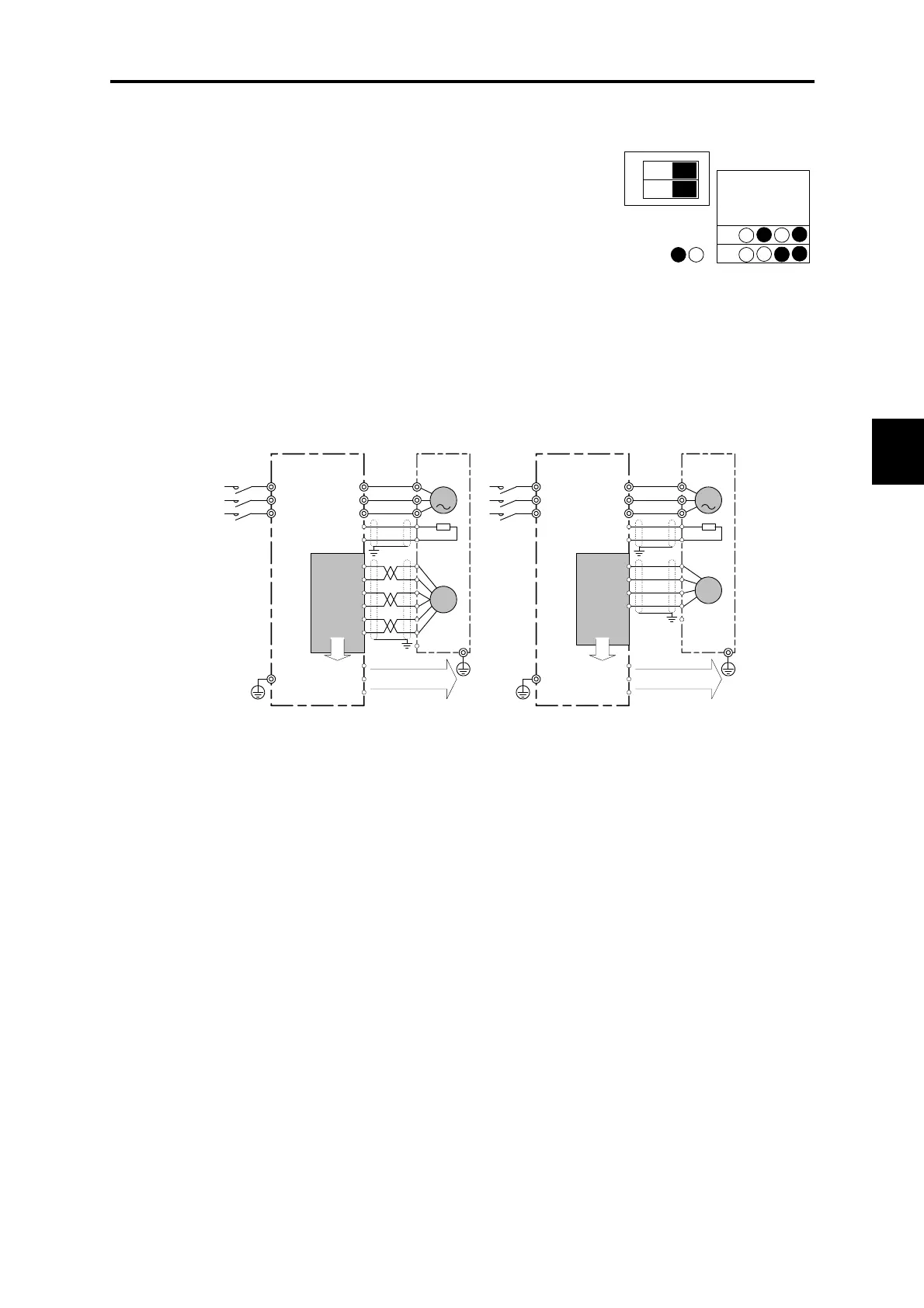
6.2.4.3 Speed control
This connection example illustrates how to drive a motor (a Fuji
servomotor, etc.) to which a line driver output type encoder or open
collector or complementary type encoder.
Since the speed is detected and calculated based on received pulses,
the PG interface expansion card must be set to SD. Since frequency
division output can be generated using FA and FB, this approach can
be used with a digital speedometer or other instrument.
When using a complementary output type encoder that supports 15 V
and 12 V output, use the inverter's PGP and PGM terminals. In this
configuration, the common line is connected to the PG interface
expansion card.
Figure 6.2.14 Figure 6.2.15
Note: As a rule, shielded wires are earthed. However, if excessive induced noise from external sources
affects the system, the effects of such noise can be reduced by connecting shielded wires to 0 V.
MOTOR
FRENIC-VG
OPC-VG1-PG(SD)
U
V
W
M
PG
[PGP]
[PGM]
[PA]
[*PA]
Main power supply
3-phase power
supply
50/60Hz
[*PB]
[PB]
[FA]
[CM]
[FB]
Open collector output
(frequency division)
[TH1]
[THC]
NTC thermistor
E
E
U
V
W
L1/R
L2/S
L3/T
MOTOR
FRENIC-VG
OPC-VG1-PGo(SD)
U
V
W
M
PG
[PGP]
[PGM]
[PA]
Main power supply
3-phase power
supply
50/60Hz
[PB]
[FA]
[CM]
[FB]
Open collector output
(frequency division)
[TH1]
[THC]
NTC thermistor
E
E
U
V
W
L1/R
L2/S
L3/T
Line driver type Open collector output and complementary output type
OFF
1
2
MODE
PD
LD
PR
SD
ON
OFF
Figure 6.2.13

 Loading...


