6.5 SX Bus Interface Card
6-91
Chap. 6
CONTROL OPTIONS
6.5.7 Data allocation addresses
6.5.7.1 Transmission format
One the following four transmission formats can be selected by the function code U11 "SX bus
transmission format selection".
(1) Standard format (U11=0)
This is the basic format which allows for monitoring of the motor speed and operation status as well
as read and write of four function codes for each (specified by the link No.).
(2) UPAC compatible format (U11=1)
This format provides the control variables which can be used for the UPAC option card
(OPC-VG1-UPAC) as fixed frame. Two function codes can be read and written for each.
(3) Monitoring format (U11=2)
This format is dedicated for monitoring and eight function codes can be read, but not be written.
(4) Standard format 2 (U11=3)
This is the basic format which allows for monitoring of the motor speed and operation status as well
as read and write of two function codes for each (specified by the 485No).
6.5.7.2 Area occupied and data allocation addresses
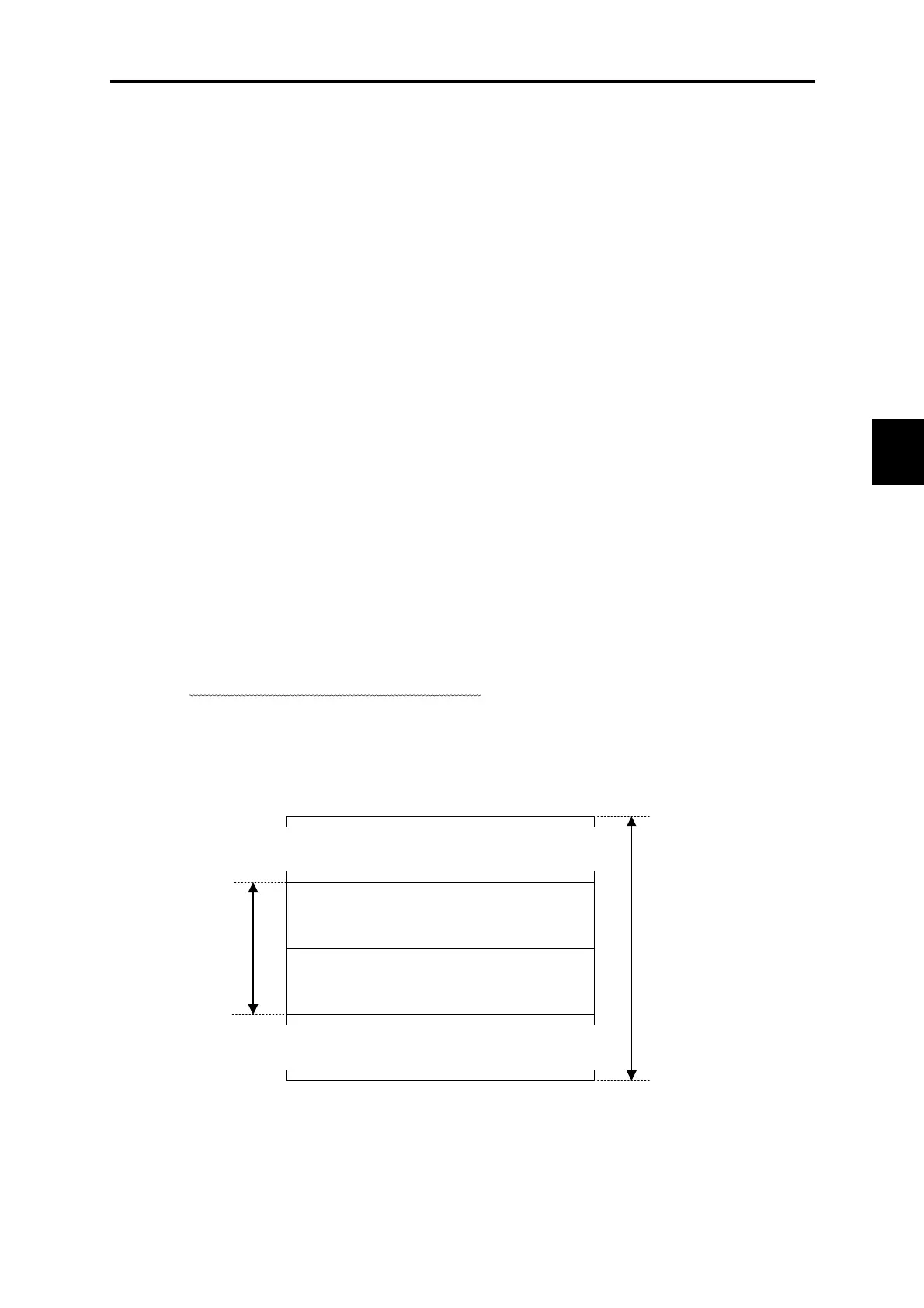
(1) Standard format (specified by link No.)
When the standard format is selected (U11=0)
, as shown in the figure below, out of the I/Q area of
the MICREX-SX, 16 words are used for each FRENIC-VG, with the lower 8 words are used for
read and upper 8 words are used for write.
(MICREX-SX ← FRENIC-VG) data
(8 words)
(MICREX-SX → FRENIC-VG) data
(8 words)
(MSB) (LSB)
15 14 ・・・ ・・・ 1 0
~
~
~
~
~
~
~
~
16 words
MICREX-SX
I/Q area
Figure 6.5.17

 Loading...


