6-250
6.15.2.2 Specifications
If the rotary switches (SW1, 2) on the option are not set correctly, the system will not operate properly. Set as
indicated below, taking care to ensure that all settings are correct.
Set the rotary switches (SW1, 2) on the option with the inverter power OFF.
Table 6.15.1 Hardware Specifications
Item Specifications
Name E-SX Bus Interface Option
Transmission specifications E-SX bus slave, I/O transmission
Transmission speed 100 Mbps
Distance between stations Maximum 100 m
Total extension distance Maximum 1,000 m
E-SX bus consumption
current
Normal operation: Maximum 6 mA, bypass operation (inverter power OFF):
Maximum 93 mA
Number of words occupied
in transmission
16 words (I area 8 words / Q area 8 words)
Terminals / bus cable IN, OUT / E-SX bus cable *NU1C-P3 (0.3 m) - NU1C-A0 (100 m)
Rotary switches RSW 1, 2 Station address setting, any station address from 1 to 283 can be assigned.
Status display LED
RUN, ERR
Status of local station (running/error) is indicated by LED
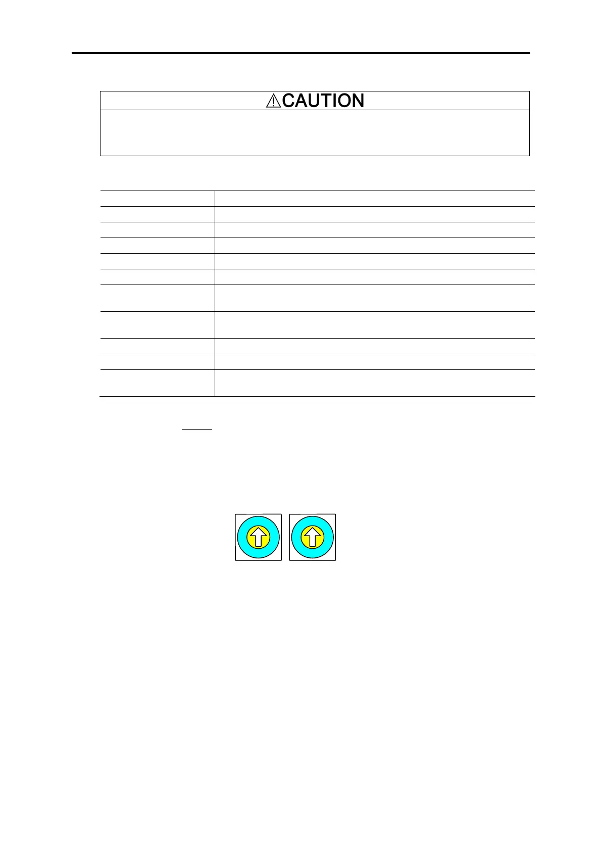
(1) Rotary switches SW1, 2
The station address is set with rotary switches SW1 and SW2 on the option board. The display is
hexadecimal, with "SW1" corresponding to the upper 4 bits and "SW2" corresponding to the lower 4 bits.
For the E-SX bus station address, read as a decimal display.
Example: For station address 194, this is C2 (h), and SW1 = C, SW2 = 2 are set.
Figure 6.15.1 Station Address Setting Switches
* Set the same address as the E-SX bus address set in the MICREX-SX system definitions. The address assigned
from MICREX-SX will be the actual E-SX bus address, so this may differ from the set values of these rotary
switches. (This can be checked in Function Code U13 "SX Bus Address Monitor".)
* When multiple units are used, make sure that duplicate E-SX bus addresses are not set.
* The factory defaults are SW1 = 0, SW2 = 0 (station address 00 (h)). In this case, the station address set in the
"Expert (D300win)" support tool system definitions is set (no degenerate system startup). If there is degenerate
system startup, a heavy alarm will occur on the MICREX-SX.
* SW1 and SW2 settings are detected during "power on" and "reset" of the E-SX bus (MICREX-SX).
0
8
4
C
A
2
E
6
1
9
5
D
F
7
3
B
0
8
4
C
A
2
E
6
1
9
5
D
F
7
3
B
SW1 SW2
SW1 : Upper 4 bits
SW2 : Lower 4 bits

 Loading...


