6-130
6.6.5.2 Connection diagram of direct parallel connection control system
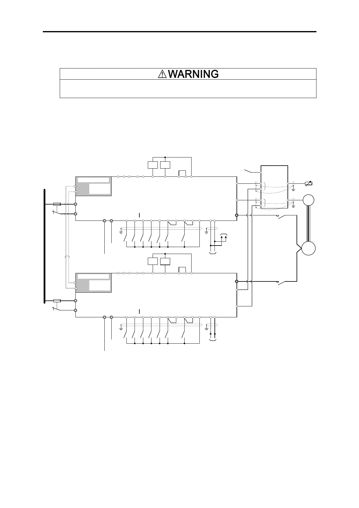
6.6.5.2-1 Double-multiplex direct parallel connection
・ For safety, design the external circuit so that all inverter units should coast to stop when an alarm occurs (30x
operation).
The following shows an example of two inverters used in direct parallel connection.
This connection diagram shows a configuration which has considered operation with reduced number of
units. When operation with reduced number of units will not be conducted, elimination of inverter output
contactors and simplification of operation sequence is possible.
OPC-VG1-TBSIS
TX
o33=2
o34=1
o50=0
→[RDY]
→[ALM]
[Y5A]
[Y5C]
[30A]
[30B]
[30C]
Inverter
ready to
run
Alarm
output
(for any
alarm)
INV1
FRENIC-VG
Stack
Master
[BX]
[CM]
BX1X
R0,T0
R1,T1
[M-CH2]
MCH1X
[FWD]
FDX
[RESET]
RSTX
[REV]
RDX
[PG-CCL]
PGCL1X
[MT-CCL]
MTCL1X1
[11]
[12]
[RT1]
[TH1]
[PGP]
Slave
52-1
IM
PG
RX
U,V,
W
[PGM]
[PA]
[PB]
[THC]
P(+),N(-
)
DCF1,2
DCF1
OPC-VG1-TBSIS
TX
o33=2
o34=1
o50=1
[CM]
BX2X
R0,T0
R1,T1
[M-CH2]
MCH2X
[FWD]
FDX
[RESET]
RSTX
[REV]
RDX
[PG-CCL]
[MT-CCL]
[11]
[12]
[TH1]
[PGP]
RX
U,V,
W
[PGM]
[PA]
[PB]
[THC]
P(+),N(-
)
DCF1,2
DCF2
52-2
NTC
MCA-VG1
-CPG
CH1
CH2
SEL
MCH2X
Optical fiber cable
Speed
setting
DC common
※
[RT1]
[RUN]
[CMY]
Inverter
running
[CM]
[PLC]
+
-
→[RDY]
→[ALM]
[Y5A]
[Y5C]
[30A]
[30B]
[30C]
[BX]
[SW-M2]
+
-
INV2
FRENIC-VG
Stack
Slave
[RUN]
[CMY]
[CM]
[PLC]
+
-
[SW-M2]
Motor M2
selected
+
-
PGCL2X
MTCL2X
1
For the fans
Auxiliary power input
[NTC-CCL][NTC-CCL]
RUN
1X
M12
X
RUN
2X
M22
X
Inverter
ready to
run
Alarm
output
(for any
alarm)
Inverter
running
Motor M2
selected
For the control circuit
For the fans
Auxiliary power input
For the control circuit
Speed
setting
*Be sure to connect inverter units to the DC common.

 Loading...


