6.10 Synchro Interface
6-213
Chap. 6
CONTROL OPTIONS
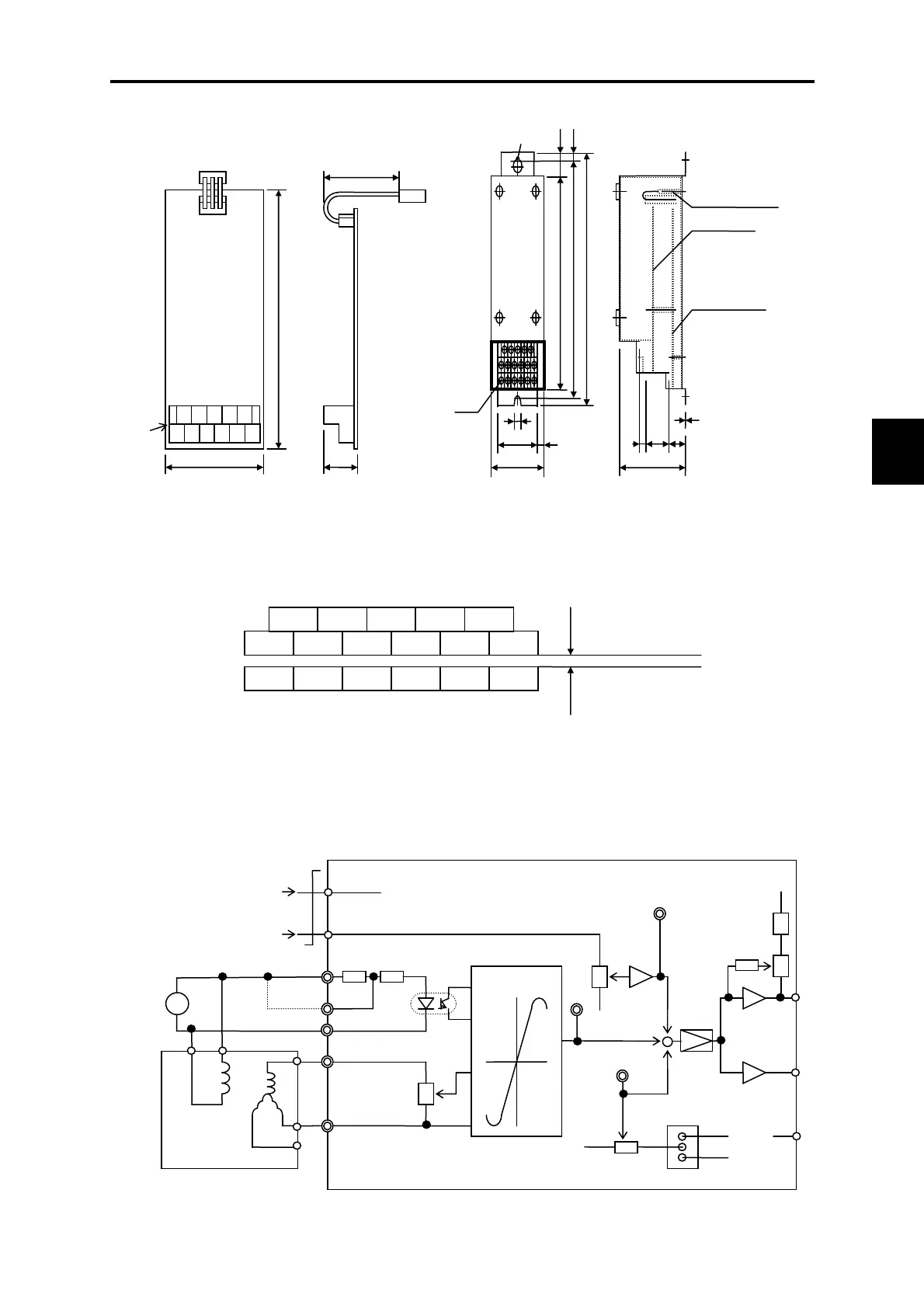
6.10.3 External dimension diagram
Unit: mm Unit: mm
Figure 6.10.1 OPC-VG1-SN
External Dimensions
Figure 6.10.2 MCA-VG1-SN
External Dimensions
■Terminal block layout
Figure 6.10.3 MCA-VG1-SN Terminal Block Layout
6.10.4 Internal block diagram
Figure 6.10.4 Internal Block Diagram
OPC-VG1-SN
terminal block (11-M3)
Motherboard
terminal block (6-M3)
S4 S3 SY2 UL V
N15M P15S3 S2 S1
S2 S1 SY1 UH
1
S2
S1
M
50/60H
Synchronous
rectification
+
+90
-90
-
-1
-1
3
2
UH
UL
V
SY1
SY2
VR
3
1
2
VR2
R1 R2
S1
S3
S2
VR3
2
1
3
M
M
CH2
CH3
-1
-1
VR4
2
3
1
S3
S4
S2
P
N
1
2
3
SC1
Potential auxiliary input
(position voltage signal input)
Synchro transmission
VR1
CH1
M
~
130
70
50
22.6
Terminal block
11-M3
Connecto
(CN1)
23
7.5 195
170
210
R3
R6
17-M3
6
OPC-VG1-SN
Motherboard
1.2
833
10
9
50
70
MCA-
VG1-SN

 Loading...


