6.1 Common Specifications
6-15
Chap. 6
CONTROL OPTIONS
6.1.4.6 Installing a field bus interface card
The following options ("interface card") can be connected to C port (CN6) on the control printed circuit
board.
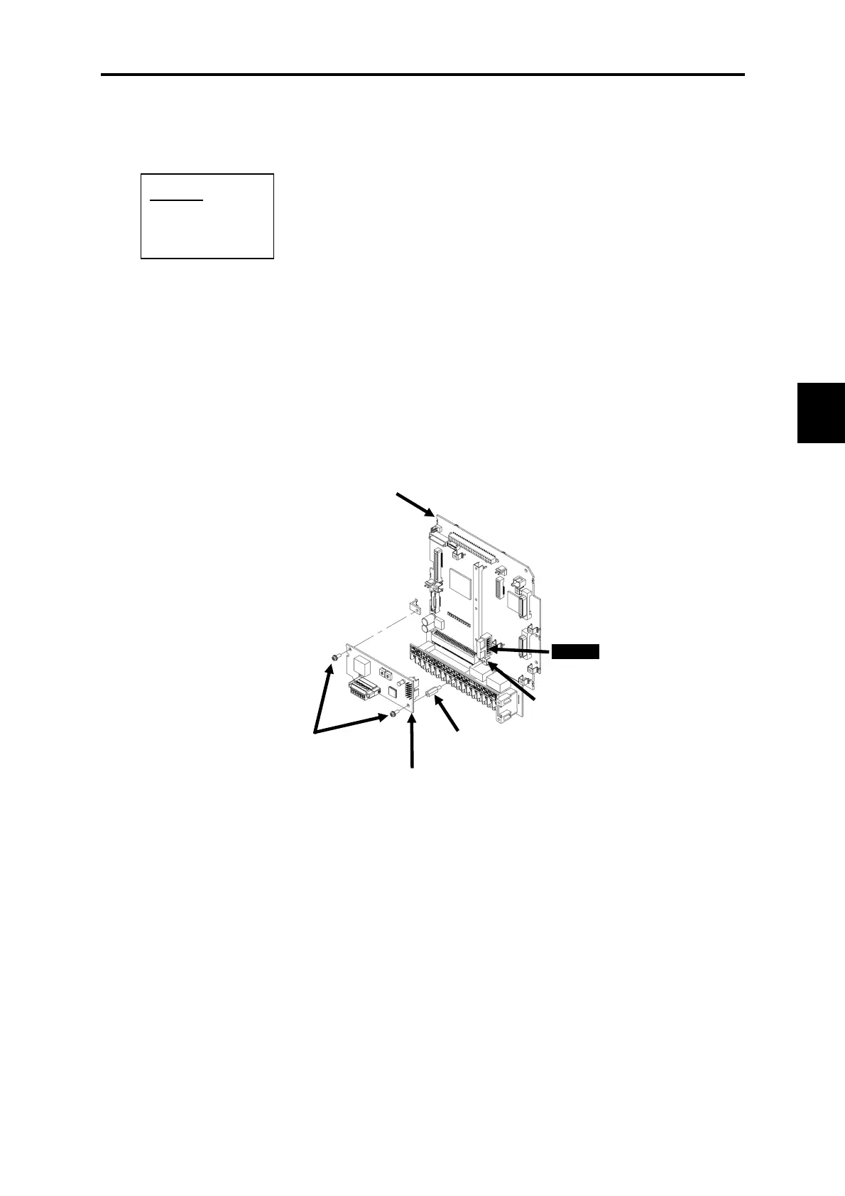
Installation procedure
(1) Attach one spacer (b) included with the interface card to the option mounting fixture (a) on the
control printed circuit board.
(2) Install the interface card so that connector CN1 (on the back of the interface card) connects to C port
(CN6) on the control printed circuit board.
(3) Tighten the two included screws (c) to secure the interface card in place.
(4) Referring to Figures 6.1.2 and 6.1.3 "Removing the Front Cover," reverse the removal procedure to
mount the front cover.
Figure 6.1.14 Installing an Interface Card
Options
OPC-VG1-PVP
OPC-VG1-DEV
C port
c
a
b
Interface card
Control printed
circuit board

 Loading...


