Revision 1 23 9/10/2019
2.6.2 Read/Rate Aperture Strip
The Read/Rate aperture strip is used to control the quantity of gas that is actually passes
onto the sensing tape. If the phosgene concentration in the sample gas is high, it may be
necessary to reduce the quantity of gas that passes onto the tape to react with the reagent on
the tape, otherwise the rate of color change will be too fast for the system to correctly analyze
the sample and poor results will be obtained. Likewise, if the phosgene concentration in the
sample gas is low, it is necessary to allow more sample gas to pass onto the tape to allow the
rate of colour change to be high enough to produce reliable results. The size of the aperture
in the read/rate aperture strip is small for high concentrations, and for low concentrations it is
large. Certain ranges do not even require an aperture strip.
Galvanic Applied Sciences provides a broad range of read/rate aperture strip sizes. The most
common aperture strip sizes are listed in Table 2-1 along with the maximum ranges they are
capable of measuring and their correct part numbers. For other ranges, please contact
Galvanic Applied Sciences.
Table 2-1: Read/Rate Aperture Strip Sizes and Associated Ranges
The range for each read/rate aperture strip size is the range between the maximum range of
the next largest aperture strip size and the maximum range of the given aperture strip size. In
addition, the system is capable of measuring ranges outside those listed in this table; please
contact Galvanic Applied Sciences for more details.
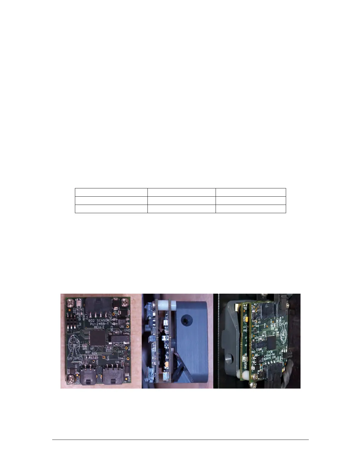
2.6.3 Sensor Block
The Sensor Block consists of two electronics boards, a microprocessor board, and a
colorimetric detector. The sensor block is shown in Figure 2-7.
Figure 2-7: Sensor Block (From Left: Top View, Side View, and Installed View)