190-01115-01 G3X™/G3X Touch™ Avionics Installation Manual
Rev. AV Page I-2
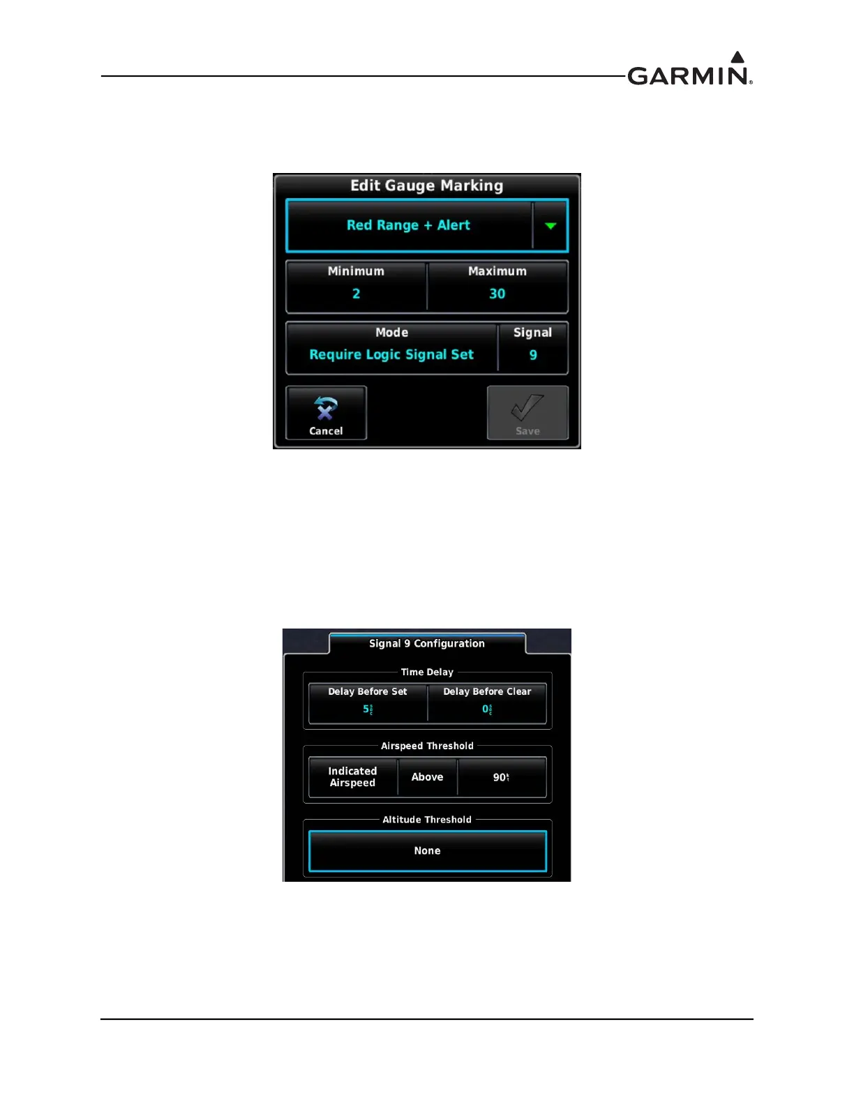
2. The Red Range + Alert Gauge Marking (Figure I-3) extends from 2-30 degrees, and carries an
associated CAS message. This visible gauge marking and CAS message are only displayed when
its associated Logic Signal is “Set” (in this example, Logic Signal 9 is used)
Figure I-3 Red Range + Alert
3. The White Line Gauge Markings serve to provide a visual reference for the 10 and 20 degree Flap
positions.
4. An airspeed constraint can be added to Logic Signal 9 (Figure I-4) from the Settings Tab of the
Engine and Airframe configuration menu. The result of this configuration is that Logic Signal 9 is
“Clear” when below 90 Knots. A 5 second delay is added in this example, although this is not
required.
Figure I-4 Signal 9 Configuration
5. The preceding configuration settings result in the Red Range + Alert Gauge Marking and CAS
message displaying when both Flaps are within the 2-30 degree position, and airspeed is above 90
Knots. If either of these thresholds are not met, the Gauge Marking and CAS message are not
displayed.