190-01115-01 G3X™/G3X Touch™ Avionics Installation Manual
Rev. AV Page 22-17
NOTE
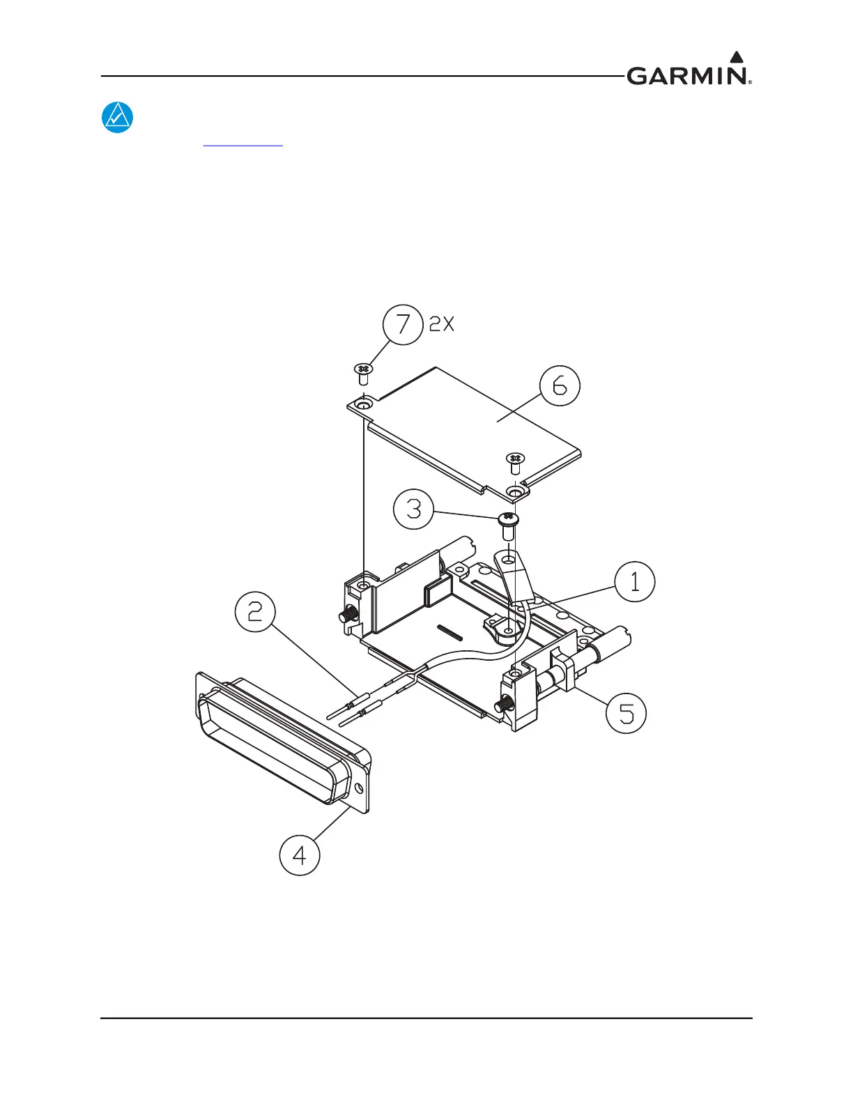
Refer to Figure 22-11 for all item numbers in the following steps 2-5.
2. Insert newly crimped pins and wires (items 1 & 2) into the appropriate connector housing (item 4)
location as specified by the installation specific wiring diagram.
3. Place thermocouple (item 1) body onto backshell (item 5) boss. Upon placing the thermocouple
(item 1) body, orient it so the wires exit downward.
4. Attach thermocouple (item 1) tightly to backshell (item 5) using screw (item 3).
5. Attach cover (item 6) to backshell (item 5) using screws (item 7).
Figure 22-11 Jackscrew Backshell Thermocouple Installation
 Loading...


