190-01115-01 G3X™/G3X Touch™ Avionics Installation Manual
Rev. AV Page 2-23
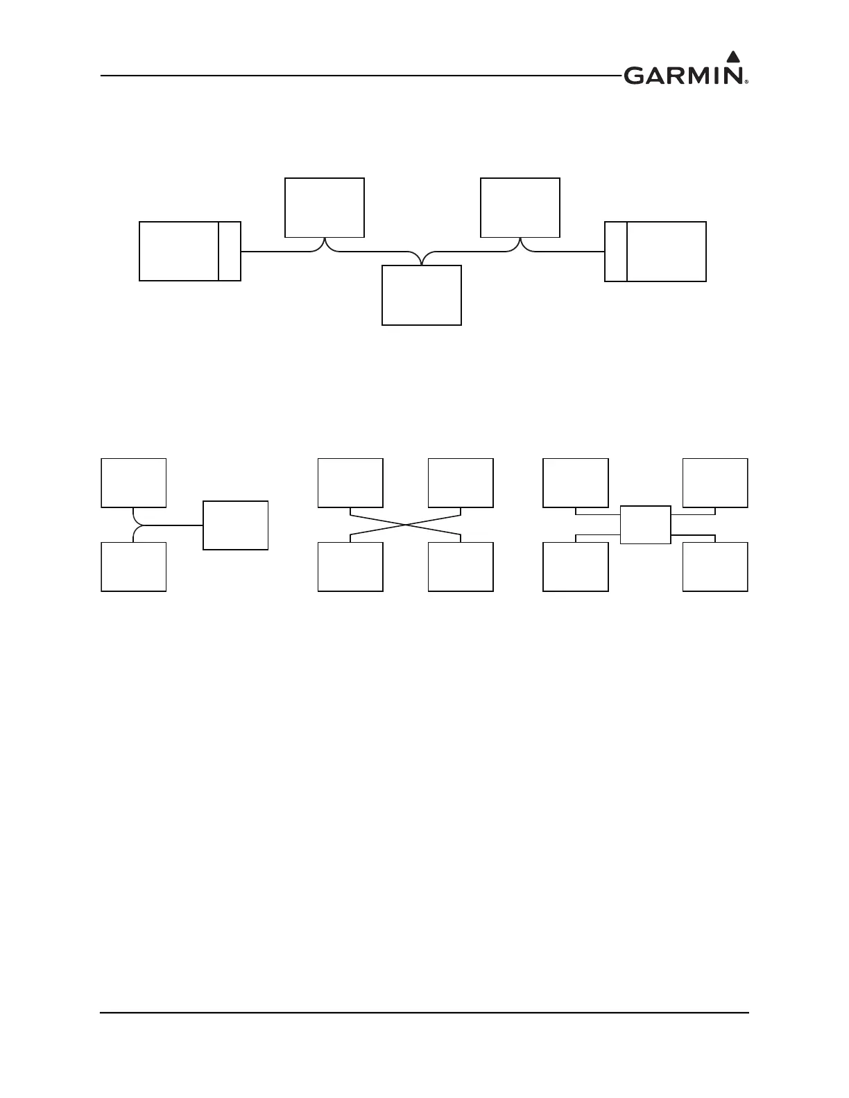
The layout of the CAN bus must be a single linear backbone with exactly two distinct end points
(Figure 2-7). Other layouts such as “star” or “Y” arrangements must be avoided. Similarly, hub devices
must not be used with the G3X CAN bus. (Figure 2-8)
Figure 2-7 Correct CAN Wiring Example
Figure 2-8 Incorrect CAN Wiring Examples
LRU
LINEAR CAN BACKBONE, DAISY-CHAINED CONNECTIONS WITH SHORT STUB
NODE LENGTHS. MULTIPLE LRUs ARE NOT CONNECTED TO BACKBONE AT
THE SAME LOCATION.
LRU LRU
LRU
TERM
LRU
TERM
LRU
LRU
LRU
AVOID “T” OR “Y” SHAPE
LRULRU
LRU LRU
AVOID STAR SHAPE
LRULRU
LRU
LRU
HUB
DEVICE
DO NOT USE THIRD-PARTY
HUB DEVICES