190-01115-01 G3X™/G3X Touch™ Avionics Installation Manual
Rev. AV Page 2-25
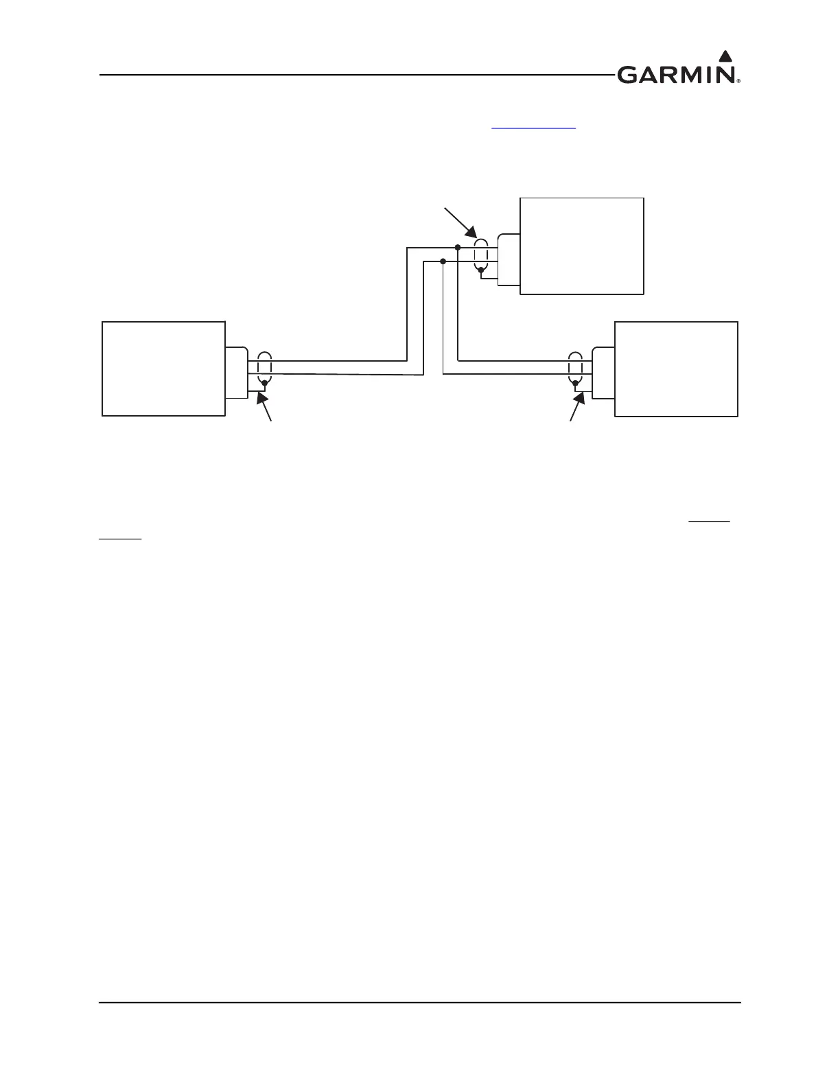
The shields for each CAN bus wire segment should be interconnected, forming a continuously connected
shield from one end of the CAN bus to the other (Figure 2-9 and Section 22-13
). At minimum, the CAN
bus shield should always be grounded to the device connector backshells at the two extreme ends of the
bus, but it is acceptable to also ground the shield at any or all other devices on the CAN bus.
Figure 2-9 CAN Bus Shield Grounding
For proper CAN bus operation, it is important for all devices on the CAN bus to share a common power
ground reference. Connect all LRU power ground pins to a single common ground point - do not use local
ground points or use the aircraft structure as a ground return path.
ALL WIRING SHOWN IS TWISTED SHIELDED PAIR
ALL WIRING SHOWN IS TWISTED SHIELDED PAIR
CAN BUS TERMINATION
CAN-H
CAN-L
SHIELD GROUND
JXXX PXXX
CAN BUS TERMINATION
CAN-H
CAN-L
SHIELD GROUND
PXXX JXXX
SHIELD GROUNDED AT CAN BUS TERMINATIONS, REQUIRED
SHIELD GROUNDED AT CAN BUS TERMINATIONS, REQUIRED
DAISY-CHAINED
LRU ON CAN BUS
CAN-H
CAN-L
SHIELD GROUND
PXXX JXXX
SHIELD GROUNDED AT EACH
DAISY-CHAINED LRU, RECOMMENDED
DAISY-CHAINED LRU, RECOMMENDED