190-01115-01 G3X™/G3X Touch™ Avionics Installation Manual
Rev. AV Page 2-27
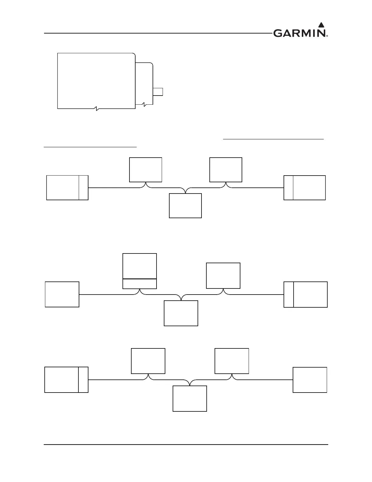
Figure 2-13 CAN Bus Termination for GTR 20/200
Both ends of the CAN bus should be terminated (Figure 2-14), but devices that are not at the ends of the
CAN bus should not be terminated (Figure 2-15).
Figure 2-14 Correct CAN Bus Termination Example
Figure 2-15 Incorrect CAN Bus Termination Examples
NOTE: JUMPER (BETWEEN PINS 25 & 26) REQUIRED NOTE: JUMPER (BETWEEN PINS 25 & 26) REQUIRED
WHEN GTR 20/200 IS LOCATED AT END OF CAN BUSWHEN GTR 20/200 IS LOCATED AT END OF CAN BUS
CAN_TERM_A 25CAN_TERM_A 25
CAN_TERM_B 26CAN_TERM_B 26
GTR 20/200GTR 20/200
CAN BUS HI 7CAN BUS HI 7
CAN BUS LO 6CAN BUS LO 6
P2001P2001
LRU
LRU
CORRECT - CAN BUS TERMINATED AT EACH END OF BACKBONE
LRU LRU
LRU
TERM
TERM
INCORRECT - ONE OF THE TERMINATIONS IS NOT AT END OF BACKBONE
LRU
LRU
LRU
LRU
LRU
TERM
TERM
INCORRECT - ONLY ONE END OF BACKBONE IS TERMINATED
LRU
LRU
LRU LRU
LRU
TERM


 To Next Page