190-01115-01 G3X™/G3X Touch™ Avionics Installation Manual
Rev. AV Page 30-223
Through the use of logic signals, complex behaviors can be generated, including:
• Oil pressure alerts that are inhibited below a specific engine RPM
• Engine RPM limits that change based on oil temperature
• Alerts for prohibited combinations of engine RPM and manifold pressure
• Gauge range markings that appear only when a discrete input is active
• Discrete inputs that generate an alert only when another gauge is within a certain range
• Engine temperature limits that change after engine start or at high altitude
• Engine RPM or manifold pressure limits that change after a period of time ("5-minute takeoff
power")
• Alerts for incorrect flap position based on airspeed
• Alerts for incorrect trim position prior to takeoff
See Appendix I
for Advanced Gauge Configuration examples.
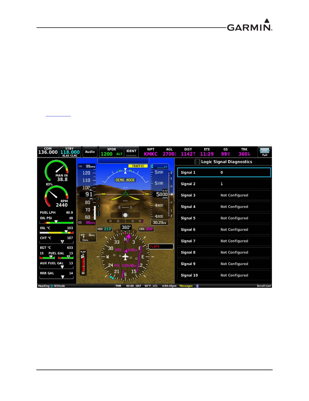
To assist with logic signal configuration, a diagnostic page showing the current state of each configured
logic signal is provided (see Figure 30-73). To access logic signal diagnostics from config mode or from
the main menu in normal mode, select Diagnostics > Logic Signals.
Figure 30-73 Logic Signal Diagnostics Page