190-01115-01 G3X™/G3X Touch™ Avionics Installation Manual
Rev. AV Page H-98
Flight Planning–The flight planning fields adjust the default values (cruise speed and fuel flow) used in
normal mode for flight planning calculations (ETE, Leg Fuel, etc.).
Aircraft Identifier–The aircraft identifier is used in the data log file and on the Flight Log page, it can be
entered using the FMS Joystick.
G Meter–The G-Meter fields allow for setting the minimum and maximum G values displayed on the PFD
G-meter. The G-meter may be displayed at any time on the PFD Setup page. Not entering any values, or
clearing the values, disables the G-Meter entirely. Setting Auto Display to On allows the G-Meter to
appear in place of the HSI when G-loads on the aircraft exceed a fixed threshold (setting Auto Display to
Off disables Auto Display of the G-Meter).
Map Symbol–The aircraft symbol that is displayed on the Map page can be selected from five different
vehicles that are stored internally to the unit. Additional vehicles may be downloaded from
www.garmin.com/vehicles
.
NOTE
To use a downloaded .srf aircraft symbol, create a ‘Vehicle’ directory on the SD card(s),
then copy the .srf file to the new ‘vehicle’ directory. For installations with multiple GDUs,
the .srf file must be present on each SD card inserted into each of the GDUs. If the file is
not present, the GDU will use the default black-and-white airplane symbol.
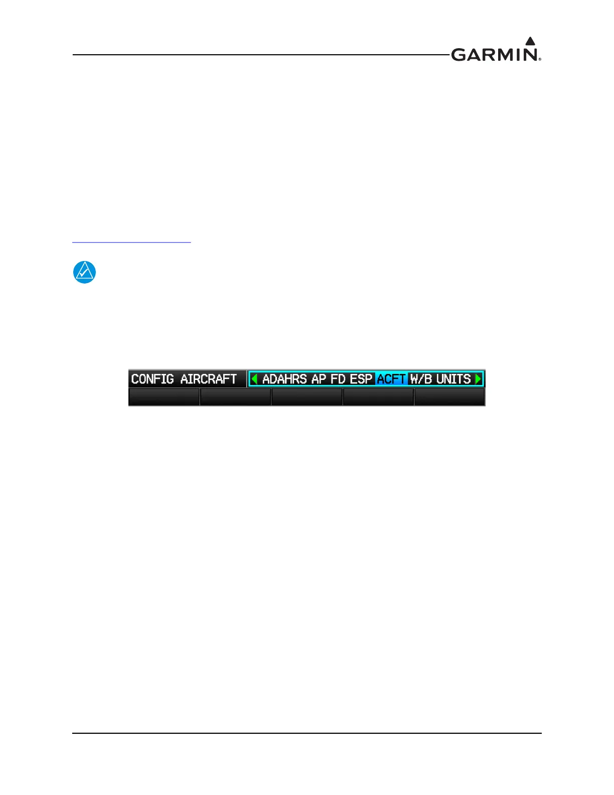
1. In configuration mode, use the FMS Joystick to select the ACFT Page.