5-20 120 Series Maternal/Fetal Monitor Revision B
2015590-001
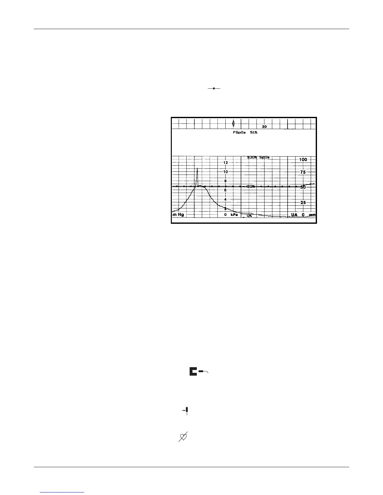
Setup Procedures: FSpO2 Setup Screen
%O2 Trace
This setting enables or disables the printing of the %FSpO2 trend on the bottom grid
of the strip chart paper.
On: The %FSpO2 trend is printed as a beaded trace on the bottom (or right) grid
annotated by %FSpO
2 .
Off: The %FSpO2 trend is not printed.
Figure 5-10. FSpO
2 Trend
FSpO2 Display Area
Single versus Dual Display of SpO2
If FSpO2 is monitored while MSpO2 is inactive, FSpO2 displays in the Additional
Parameters Area. Refer to Figure 6-4. When dual SpO
2 monitoring occurs, FSpO2
information is displayed in the Waveform Area beneath the MSpO
2 area. Any
waveform labels (speed, lead, scale) move to the left of the FSpO
2 area. The
waveform area, which would otherwise display about 4 seconds of information, is
reduced to show approximately 2.5 seconds of waveform data. Refer to Figure 6-5.
FSpO2 Status Icons
A status icon may appear above the %FSpO2 value to provide additional
information. Usually the message area will be blank; however, the icons
representing
Sensor Unplugged, Sensor Lifted, or Searching for Fetal Pulse can appear.
Sensor Unplugged – This icon appears whenever: the FSpO
2 sensor is
disconnected from the fetal patient module cable; when the fetal patient module
cable is disconnected from the monitor; or when an invalid FSpO
2 sensor is
connected to the fetal patient module cable.
Sensor Lifted – This icon appears whenever the sensor is not making
adequate contact at the sensor site on the fetus.
Pulse Search – This icon is displayed when the monitor is attempting to
locate the fetal pulse. During successful monitoring, the message area is blank.
)
()

 Loading...


