Revision B 120 Series Maternal/Fetal Monitor 4-27
2015590-001
Theory of Operation: DSP Board
Front Panel Switch Interface
This section consists of simple buffers (U2, U3) for the incoming switch closures as
well as static protection resistors (RN10, RN11) and capacitors.
An additional latch (U4) is used to control the recorder LED line as well as the video
pattern, stop scan, and invert lines.
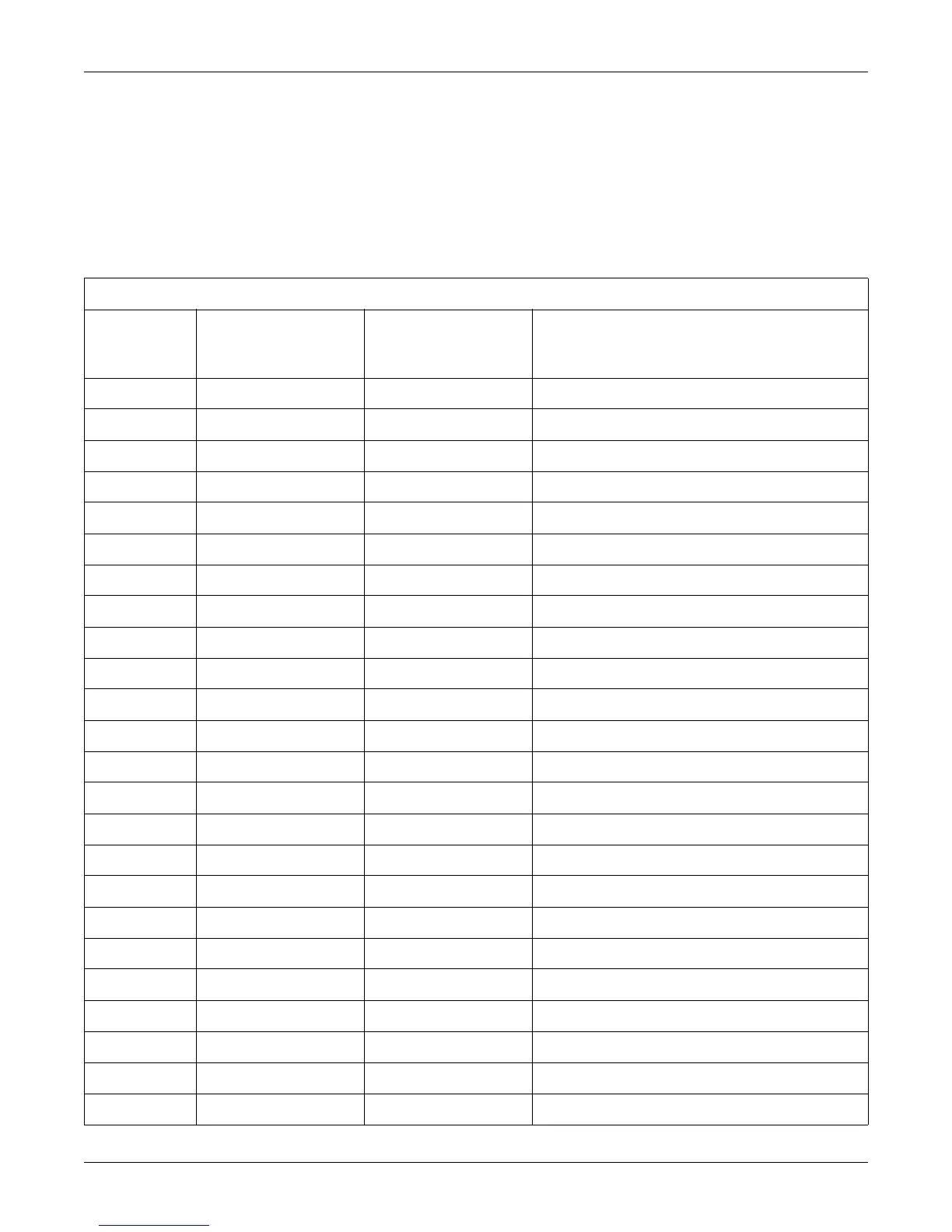
Table 4-13. Front End Connector J1
Pin Number Signal Name
Signal Type
(Relative to Main
Motherboard
Signal Description
1 GND Output Digital Ground
2 BD6 I/O Status/Control Bus Bit 6
3 BD7 I/O Status/Control Bus Bit 7
4 CS0/ Output Status/Control Bus Chip Select 0
5 CS1/ Output Status/Control Bus Chip Select 1
6 CS2/ Output Status /Control Bus Chip Select 2
7 CS3/ Output Status/Control Bus Chip Select 3
8 +5V Output +5 V Logic Supply
9 BRD* Output Status/Control Bus Read Line
10 BA1 Output Status/Control Bus Address Line Bit 1
11 RESDSP* Output DSP Board Reset Line
12 RESFR* Output Unused
13 144KHZ Input Ultrasound 144 kHz Output
14 72KHZ Input Ultrasound 72 kHz Output
15 GND Output Digital Ground
16 RESAO2 Output MSpO
2 Module Reset Line From Main Motherboard
17 +5V Output +5 V Logic Supply
18 IUPCLK Input IUP Clock from IUP Front End
19 CVRT/ Output IUP Start Conversion Line to IUP Front End
20 IUPDATA Input IUP Data Line from IUP Front End
21 No Connection — —
22 No Connection — —
23 –15V Output –15 V Supply
24 –15V Output –15 V Supply
 Loading...


