4-34 120 Series Maternal/Fetal Monitor Revision B
2015590-001
Theory of Operation: DSP Board
Recorder LED Board Interface
This section applies only to newer monitors with the built-in strip chart recorder
light.
A single DSP Board signal (RECLED*) is routed through the switch panel to the
Recorder LED Board (No. 2002570) to control LED current. This signal drives the
base of a transistor acting as a high-side switch. When enabled, +5 V flows through
each of seven parallel high-intensity amber LEDs and accompanying series current-
limiting resistors to provide a light above the strip chart recorder.
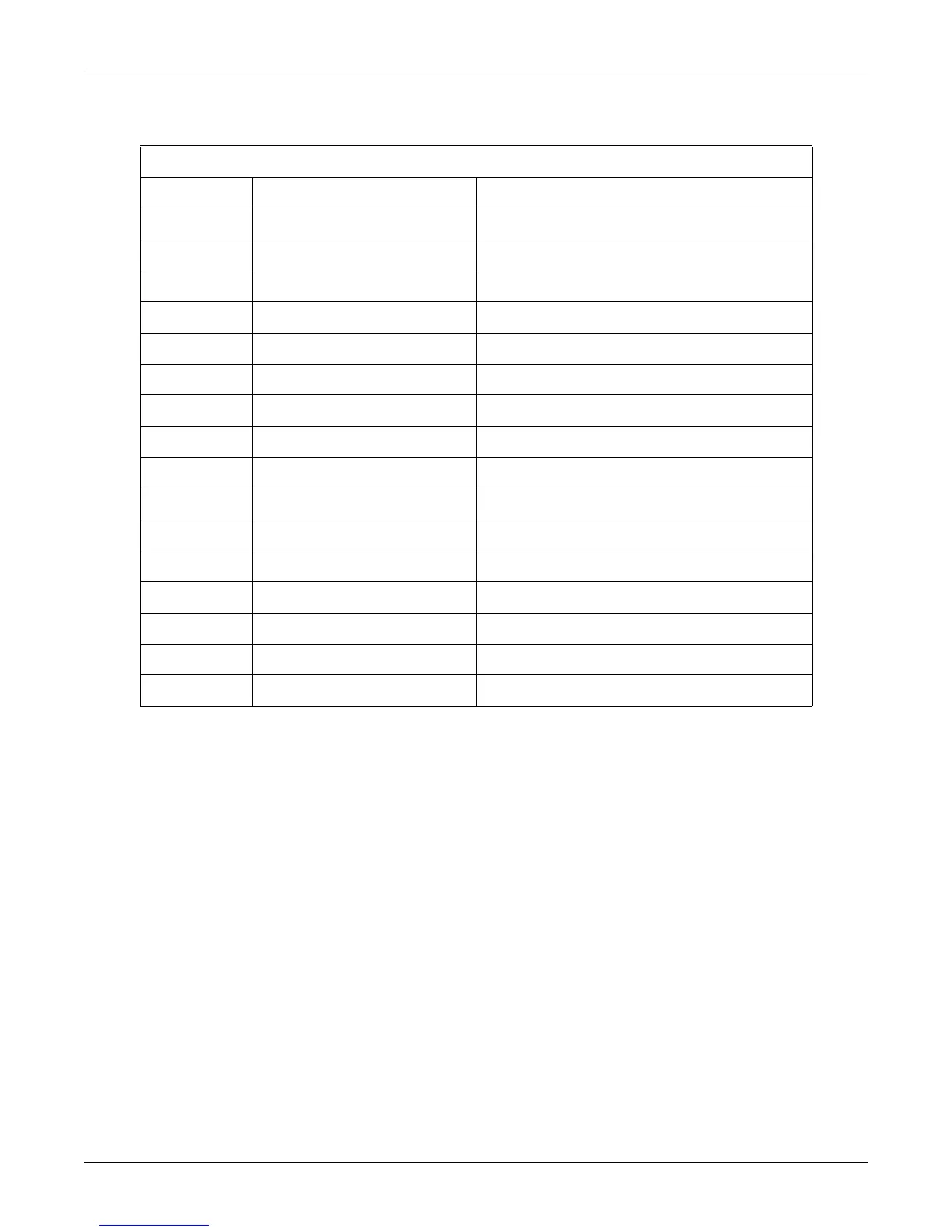
Table 4-17. EL Panel Connector J5 (for 11888 Board)
Pin Number Signal Name Signal Description
1 +12V +12 Volt Power
2 +12V +12 Volt Power
3 +5V +5 Volt Power
4 +5V +5 Volt Power
5 GND Power Ground
6 GND Power Ground
7 GND Power Ground
8 GND Power Ground
9 VSYNC Vertical Sync Line
10 GND Power Ground
11 HSYNC Horizontal Sync Line
12 GND Power Ground
13 VCK Video Clock
14 GND Power Ground
15 DATA Video Data
16 GND Power Ground