Revision B 120 Series Maternal/Fetal Monitor 3-19
2015590-001
Controls, Indicators, and Connectors: Rear Panel Description
CAUTION
NON-DESTRUCTIVE VOLTAGE—The maximum non-
destructive voltage that may be applied to the rear panel
connectors is 0 volts. Do not attempt to connect cables to these
connectors without contacting your Biomedical Engineering
Department or Information Technologies Service Representative.
This is to ensure the connectors comply with leakage-current
requirements of one of the following applicable standards:
Underwriters Laboratories UL-2601.1, Canadian Standards
Associations CSA 22.2 No. 125, or International Electrotechnical
Commission EN60601.1.
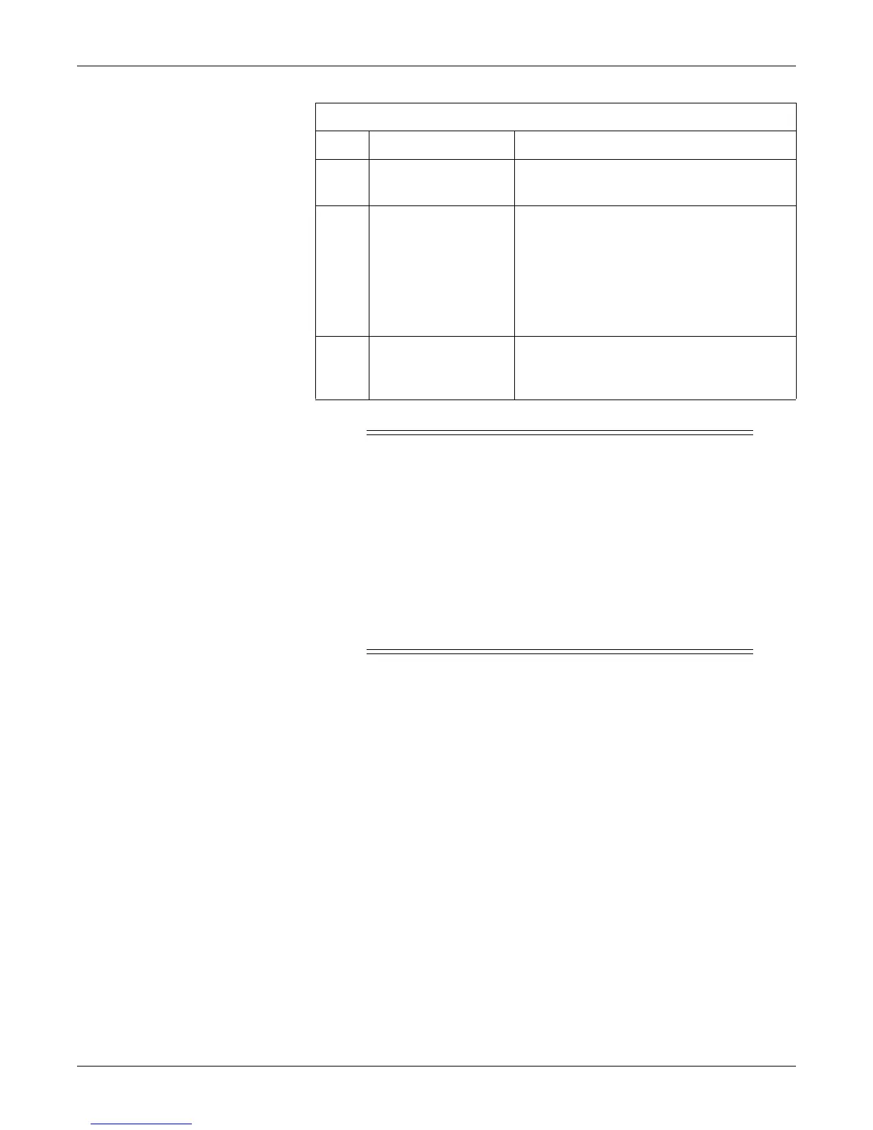
L Equipotential Lug
A binding post terminal is directly connected to the
chassis for use as an equipotentiality connection.
M
AC Voltage Selection
Switch
This switch is intended for qualified service
personnel to select a voltage range for the AC
input:
120: Accepts an AC input in the range of 100–
120 VAC.
240: Accepts an AC input in the range of 220–
240 VAC
N Power Entry Module
AC line power cord receptacle. Refer to the rear
panel markings to verify line voltage and line
frequency requirements.
Table 3-13. 120 Series Rear Panel (Standard and Optional Features)
Name Description
NOTE: Although the J104 Nurse
Call connector is physically present
on the optional communications
package, this connector is only
supported as part of the Spectra
Alerts option.

 Loading...


