4-8 120 Series Maternal/Fetal Monitor Revision B
2015590-001
Theory of Operation: Main Motherboard
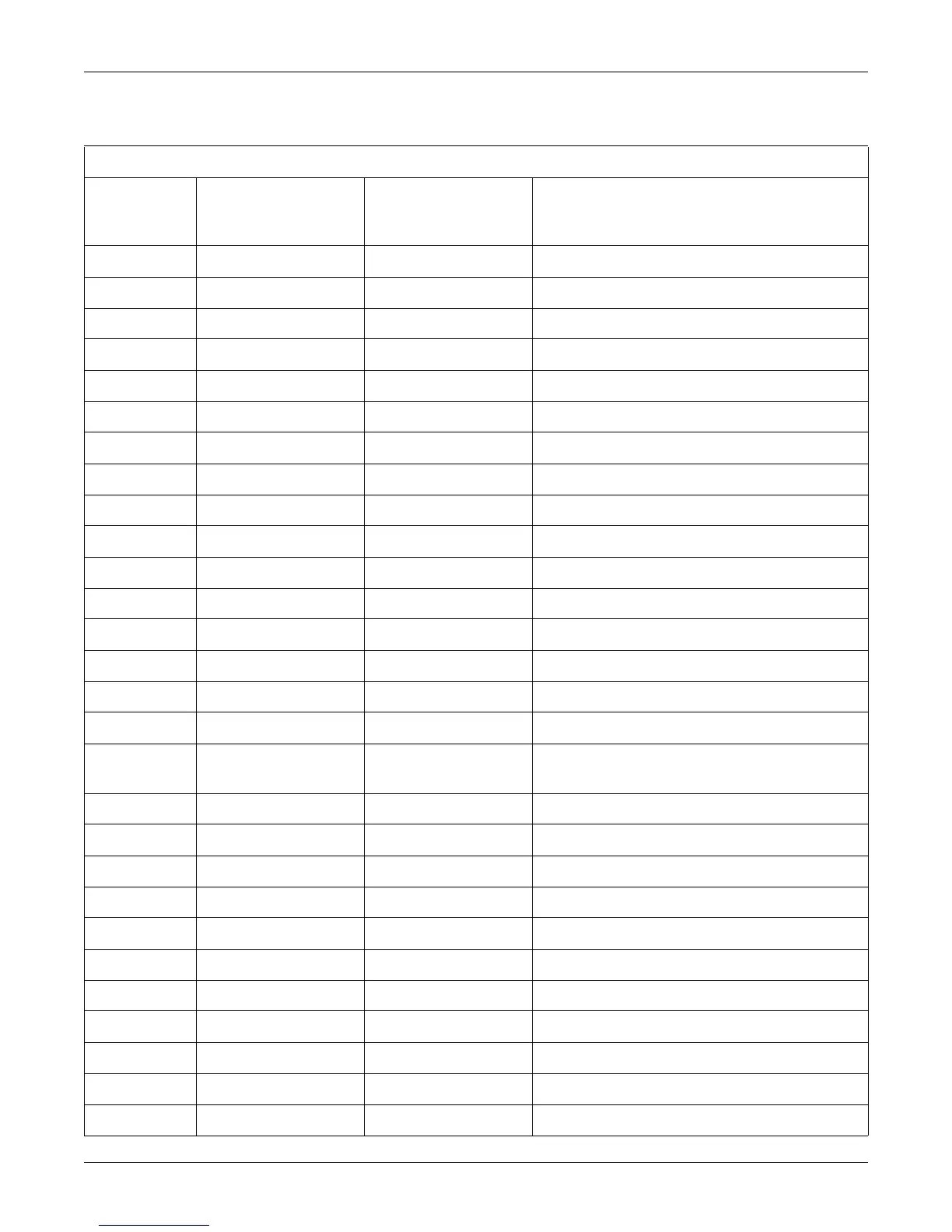
Table 4-5. DSP Board Connector J7
Pin Number Signal Name
Signal Type
(Relative To Main
Motherboard)
Signal Description
1 IRQ7/ Input Interrupt Line from DSP Board Shared RAM
2 SHEM/ Output DSP Shared Memory Chip Select Line
3 No Connection — —
4 RESA02 Output Reset Line for SpO
2 Module
5 RESDSP/ Output Processor Controlled Reset Line
6 72kHz Input 72 kHz from Front End to Sync Power Supplies
7 +15v Output +15 Volt Analog Supply
8 –15V Output –15 Volt Analog Supply
9 AGND Output Analog Ground
10 AGND Output Analog Ground
11 –15v Output –15 Volt Analog Supply
12 AGND Output Analog Ground
13 US2AUDIO Input Ultrasound2 Audio
14 GND Output Digital Ground
15 TMECG Output Telemetry MECG
16 TELMAUDIO Input Telemetry Audio
17 IRQ7/(alt) Input
Alternate Interrupt from DSP Board (Jumper Selectable
On to Processor IRQ7/ Line)
18 D0B I/O Buffered Data Line
19 D2B I/O Buffered Data Line
20 D4B I/O Buffered Data Line
21 D6B I/O Buffered data line
22 D8B I/O Buffered data line
23 D10B I/O Buffered data line
24 +5V Output +5 Volt Logic Supply
25 D12B I/O Buffered Data Line
26 D14B I/O Buffered Data Line
27 A1B Output Buffered Address Line
28 A3B Output Buffered Address Line

 Loading...


