GE Healthcare Senographe DS
Revision 1 Service Information and Procedures Class A 2385072-16-8EN
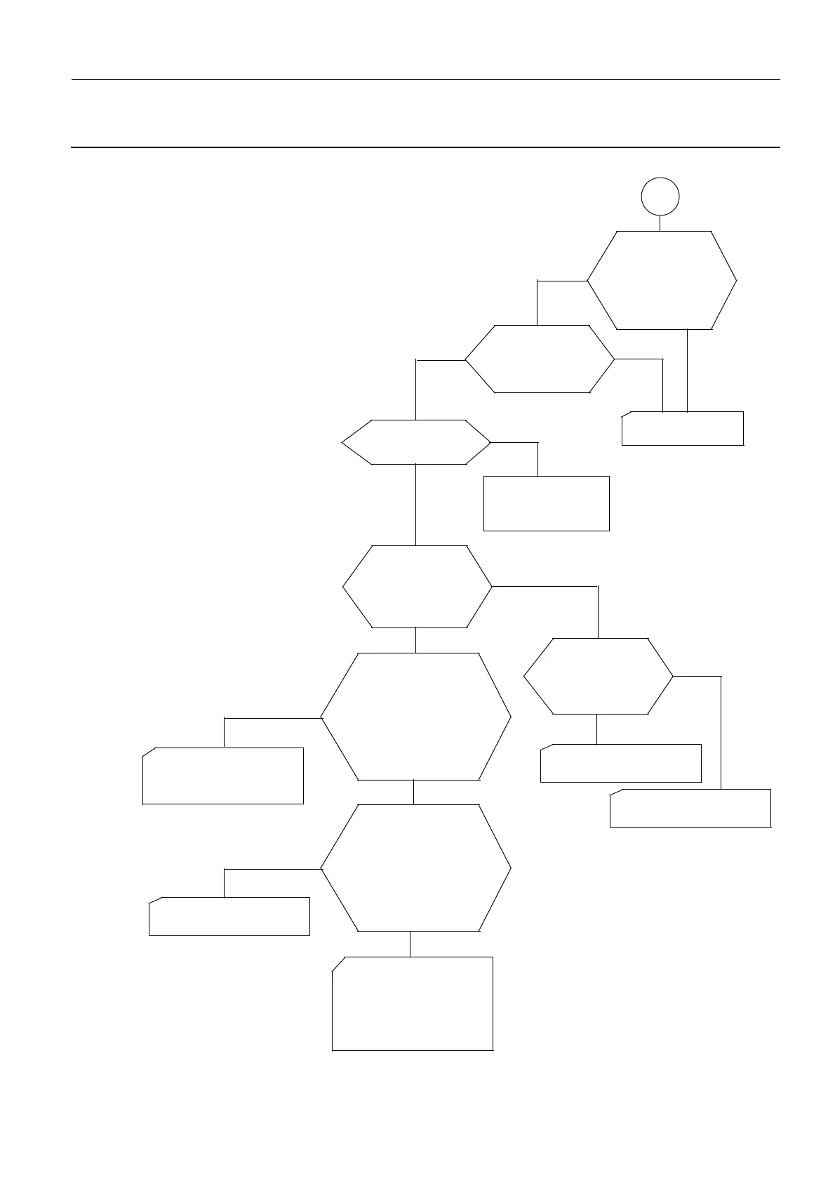
Job Card TSG A020 - Generator Power-Up Sequence Flow Charts
Page no. 1075 Chapter 9
JC-TSG-A-020.fm
2-6 Keep–Alive Voltage Checks on 200PL1 - C
200PL1: Is AC
voltage between the
IN2 voltage selection
"strap" terminals 7
and 4 or 5 and 8 at
mains voltage?
200PL1: Is AC
voltage between Xj2
and XJ7 at mains
voltage?
Mains fuses F1/F2
all OK?
Change 200PL1.
Yes
Yes
No
No
No
See Partial Power–
up Sequence
on
page 1077.
Yes
Voltage between
Generator mains and
supply switch S1
terminal at mains
voltage?
Yes
No
With mains fuses F1
and F2 removed, is
wiring continuity
between mains fuse
terminals F1–1/F2–1
and main power
contact K1 terminals
K1–1/K1–3 good?
With mains fuses F1
and F2 removed, is
wiring continuity
between main power
contact K1 terminals
K1–2/K1–4 and
200PL1 XJ2/XJ7
good?
Replace appropriate wiring
and/or appropriate fuse
holder terminals.
Replace appropriate
wiring.
No
No
Mains voltage
present on input side
of Gennerator mains
supply switch S1?
Yes
No
Check incoming mains
wiring.
Replace Generator mains
supply switch S1.
Yes
Yes
Check (and replace where
necessary) wiring between
mains fuse holders (F1/F2)
and Generator mains
supply switch S1.
C

 Loading...


