Chapter 9 Page no. 1128
JC-DR-A-189.fm
GE Healthcare Senographe DS
Revision 1 Service Information and Procedures Class A 2385072-16-8EN
Job Card D/R A189 - Interface Board
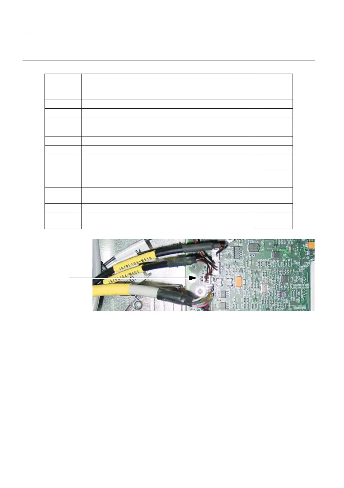
3. Ensure that jumper TP1 (3) that is to the left of the J4 connector on the Interface board is open.
4. Re-install the Gantry CPU board on the Interface board according to Replacing the Gantry CPU
Board on page 1133 in Job Card D/R A190 - Gantry CPU Board.
5. Lift the top metal panel up to release it from the left side of the framework and replace it over the
framework to hide the newly installed Gantry CPU board.
6. Switch on the Gantry electrical power.
7. Wait until the Gantry boot is complete, and check that no error has been reported.
If the Interface board is operating correctly, the LED states are as follows:
• all three of the green LEDs in the upper part of the Interface CPU board near the fiber connectors
J8, J9 and J10 (i.e. DS1, DS2, and DS3) are ON
• the green LEDs DS8 and DS11 near the J5 connector are blinking (i.e. there is network activity on
the Ethernet connection)
• all the other green LEDs near the J5 connector (i.e. DS4, DS5, DS6, DS7, DS9, DS10, DS12, and
DS13) are OFF
8. Reinstall the column cover (CPU side); refer to Job Card PHY A044 - Remove/Reinstall Gantry Cov-
ers on page 523.
Connector
Label
Description of cable
(usually identified by code on a yellow label)
Cable color
J1 J1/PL104-W116 Gray
J2 J2/PL104-W101 Gray
J3 J3/PL104-W208 Gray
J4 J4/PL104-W402 Black
J5 J5/PL104-W314 Gray
J6 J6/PL104-W216 Black
J7 J7/PL104-W217 Black
J8 W121 - PL104 - J8
(to top fiber connector)
Black
J9 W120 - PL104 - J9
(to middle fiber connector)
Black
J10 W119 - PL104 - J10
(to bottom fiber connector)
Black
J11 Empty N/A
Eth Switch-AWS
(RJ-45 connector at bottom)
Gray
3

 Loading...


