GE Healthcare Senographe DS
Revision 1 Service Information and Procedures Class A 2385072-16-8EN
Job Card D/R A403 - Capacitor Box
Page no. 1555 Chapter 9
JC-DR-A-403.fm
8. Remove screws S7 and S8, followed by screws S9 and S10 mounting the capacitor box on the
"Inverter" panel (4 mm allen wrench).
9. Remove the capacitor box.
6-2 Installation of Filtering Capacitors
1. Place the new capacitor box into position. Ensure that the holes on the side of the capacitor box line
up with the threads on the inverter panel.
2. Attach screws S7 and S8, followed by screws S9 and S10 to mount the capacitor box on the
"Inverter" panel (4 mm allen wrench).
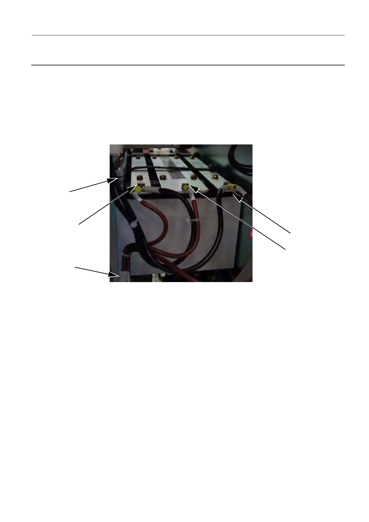
3. Connect the cables to the new capacitor box using the screws S4, S5, and S6 (8 mm open-ended
wrench) as follows:
• S4 connects the black and brown cables labeled C1+
• S5 connects the brown cable labeled C1–/C2+
• S6 connects the black and brown cables labeled C2–
S6 (C2–)
S5 (C1–/C2+)
S4 (C1+)
S9
S7

 Loading...


