GE Healthcare Senographe DS
Revision 1 Service Information and Procedures Class A 2385072-16-8EN
Job Card D/R A407 - Generator Interface Board 400-PL2
Page no. 1581 Chapter 9
JC-DR-A-407.fm
4. Ensure that all the Test Point (PT) connectors (labeled PT1, ... etc.) on the Generator Interface board
are open.
5. Ensure that all the Test Point (TP) connectors (labeled PT1 to TP53) located to the right of the XJ2
connector on the Generator Interface board are open.
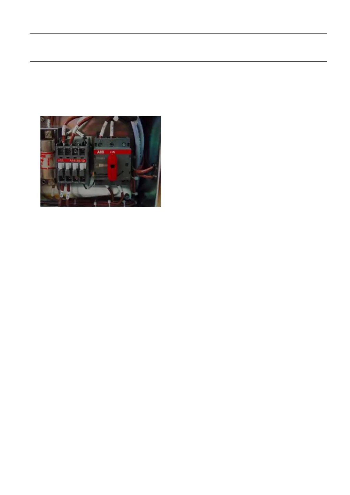
6. Switch on the electrical power supply, both from the Mains Distribution Panel in the room and on the
rotary switch in the Generator cabinet (position I).
7. Switch on the Senographe system electrical power (i.e. Generator, Gantry, and Control Station).
8. Wait until the Gantry boot is complete, and check that no error has been reported.
If the Generator Interface board is operating correctly, the LED states on the Generator Interface
board are as follows:
• yellow DS1 LED is ON
• yellow DS2 LED is ON
• yellow DS3 LED is ON
• yellow DS4 LED is ON
• yellow DS5 LED is ON
• yellow DS6 LED is ON
• yellow DS7 LED is ON
• yellow DS8 LED is ON
• yellow DS9 LED is ON
• green DS10 LED is OFF
• green DS11 LED is OFF
• green DS12 LED is ON
• green DS13 LED is ON
• green DS14 LED is ON
• red DS15 LED is OFF
9. Reinstall the Generator covers (see Job Card PHY A042 - Remove/Reinstall Generator Covers on
page 513).

 Loading...


