GE Healthcare Senographe DS
Revision 1 Service Information and Procedures Class A 2385072-16-8EN
Central Listing
Page no. 281 Chapter 3
Indicators and Switches.fm
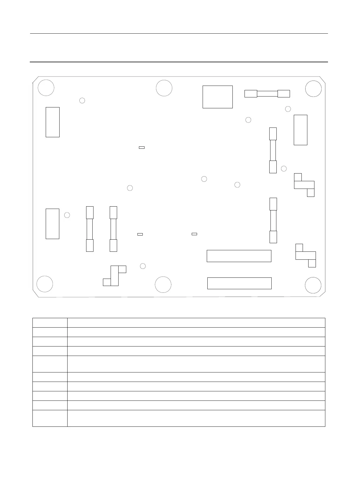
3-1. Mains Distribution Assembly
3-1-1. Mains Distribution Assembly Connectors
Connector Function
J1 240 V Supply from Primary Transformer
J2 240 V Supply to Conditioner
J3 230 V Supply from Secondary Transformer
J4 230 V AC supply to Control Station UPS via 250 V Line Filter, XP4 connector on Conditioner Cab-
inet and XJ2 connector on Gantry bulkhead
J5 AC supply to J1 connector on Detector Power Supply via XP5 connector on Conditioner Cabinet
J6 220 V to the IN connector on the Low Voltage Power Supply Board
J7 12 V from the OUT connector on the Low Voltage Power Supply Board
J8 FFDM Mains Distribution connection to XJ11 connector on Generator Interface Board 400PL2
J9 Data connection to the Service Interface (Condioner, Control Station and UPS power control but-
tons) on the Generator
J2
F1
J7
J5
TP1
F4
F5
F2
F3
J6
J4
J3
J8
J9
TP2
J1
DS1
DS8
DS9
DS7
DS6
DS5
DS4
DS2
DS3
TP3