GE Healthcare Senographe DS
Revision 1 Service Information and Procedures Class A 2385072-16-8EN
Cable Lay-out and Pin-out
Page no. 305 Chapter 3
Cables.FM
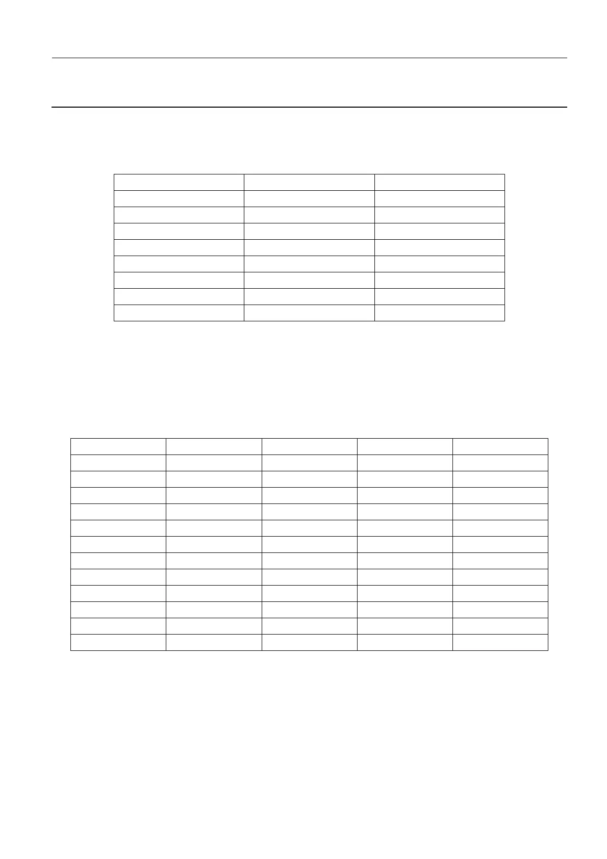
1-32. W205/206 Motor and Encoder Connect; Lift and Rotation Motors
Motor and cable assembly used in two places, with Lift Board PL201 and Rotation Board PL202.
W205: Board PL201/2 J9 to encoder U201. W206: Board PL201/2 J10 to motor M201.
1-33. W207/222 - Footswitch Cables
Lift Board PL201 J6 to Foot Switch PL202 J1.
1-34. W208 - POS-Bus1
Interface Board PL104 J3 to Lift Board PL201 J3.
Color PIN ITEM
Red J9-1 +DC 5 V
Black and Shield J9-2 GND
Blue J9-3 A-Channel
Brown J9-4 /A-Channel
Green J9-5 B-Channel
Purple J9-6 /B-Channel
White J9-7 C-Channel
Yellow J9-8 /C-Channel
PIN (PL104) Designation Type Level PIN (PL201)
PL104/J3-1 H-CAN Network CAN Diff 5 / 2.5V PL201/J3-1
PL104/J3-2 L-CAN Network CAN Diff 2.5 / 0V PL201/J3-2
PL104/J3-3 GND Ground 0 V PL201/J3-3
PL104/J3-4 H-RT line 1 RT-CAN Diff 5 / 2.5 V PL201/J3-4
PL104/J3-5 L-RT line 1 RT-CAN Diff 2.5 / 0V PL201/J3-5
PL104/J3-6 Stop motion RT 0/+5 V PL201/J3-6
PL104/J3-7 H-RT line 2 RT-CAN Diff 5 / 2.5 V PL201/J3-7
PL104/J3-8 L-RT line 2 RT-CAN Diff 2.5 / 0V PL201/J3-8
PL104/J3-9 Reset line RT 0/+5 V PL201/J3-9
PL104/J3-10 GND Ground 0 V PL201/J3-10
PL104/J3-11 H-RT line 3 RT-CAN Diff 5 / 2.5 V PL201/J3-11
PL104/J3-12 L-RT line 3 RT-CAN Diff 2.5 / 0V PL201/J3-12

 Loading...


