Chapter 3 Page no. 312
Cables.FM
GE Healthcare Senographe DS
Revision 1 Service Information and Procedures Class A 2385072-16-8EN
Cable Lay-out and Pin-out
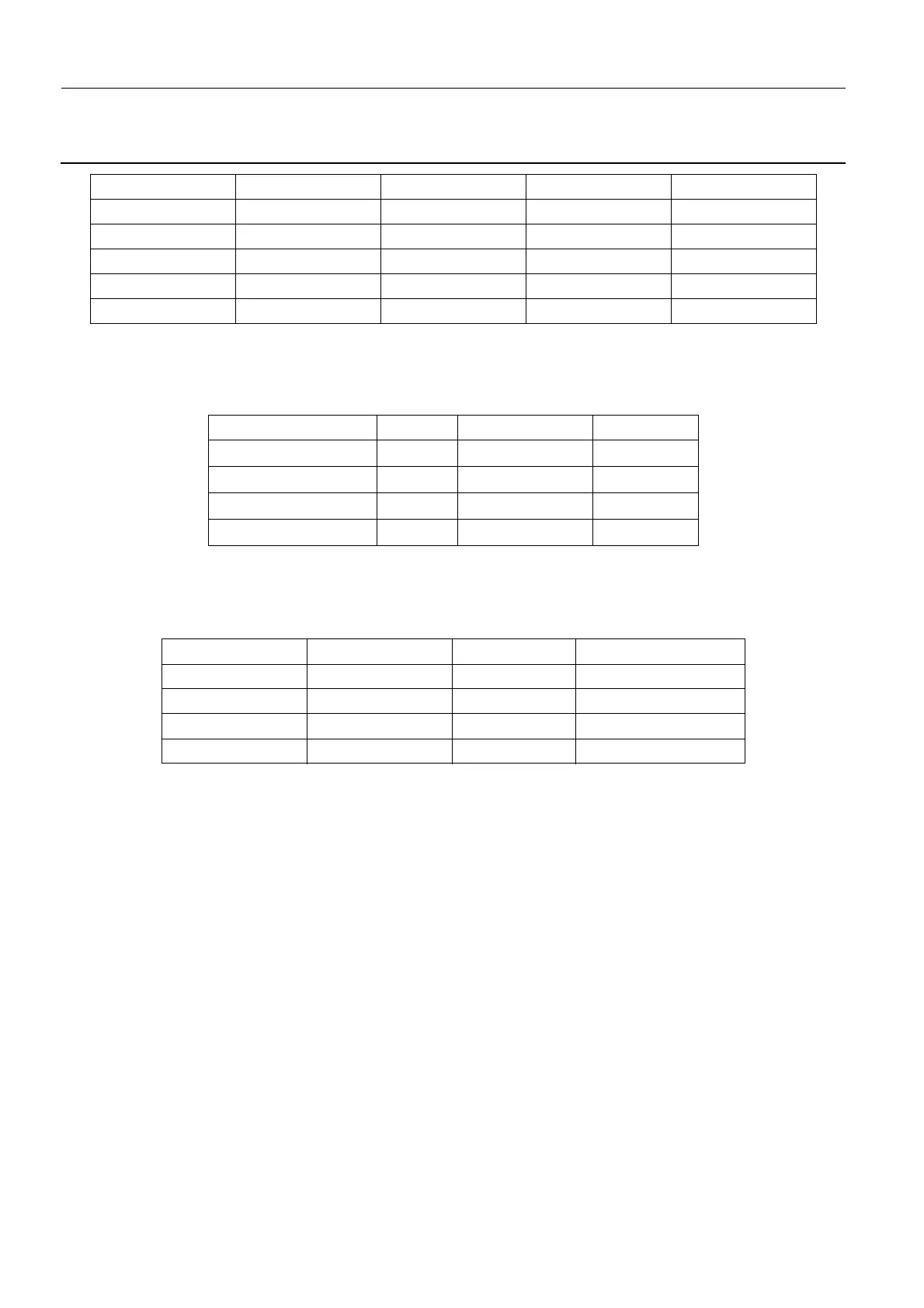
1-59. W312 - Stepper Motor to Bucky Board
Stepper Motor M302 to Bucky Board PL302 J3:
1-60. W313 - Compression Board to Bucky Board
Compression Board PL303 J9 to connector J4a, then from J2a to Bucky Board PL302 J2:
PL301/J3-7 H-RT line 2 RT-CAN Diff 5 / 2.5 V PL302/J1-7
PL301/J3-8 L-RT line 2 RT-CAN Diff 2.5 / 0V PL302/J1-8
PL301/J3-9 Not used
PL301/J3-10 GND Ground 0 V PL302/J1-10
PL301/J3-11 Not used
PL301/J3-12 Not used
Designation Type Level PIN
OUT_1A Hbridge 0 / 48 Volts J3-1
OUT_1B Hbridge 0 / 48 Volts J3-2
OUT_2A Hbridge 0 / 48 Volts J3-3
OUT_2B Hbridge 0 / 48 Volts J3-4
PIN (PL303) Designation Colour PIN (connector J4a)
PL301/J9-1 GND Red PL302/J4a-6
PL301/J9-2 Rec 0 Black PL302/J4a-3
PL301/J9-3 Signal 1 Yellow PL302/J4a-4
PL301/J9-4 Signal 2 Green PL302/J4a-5

 Loading...


