GE HEALTHCARERAFT VOLUSON E8 / VOLUSON E6
D
IRECTION KTD102576, REVISION 7 DRAFT (AUGUST 23, 2012) SERVICE MANUAL
5-4 Section 5-2 - General Information
Section 5-2 General Information (cont’d)
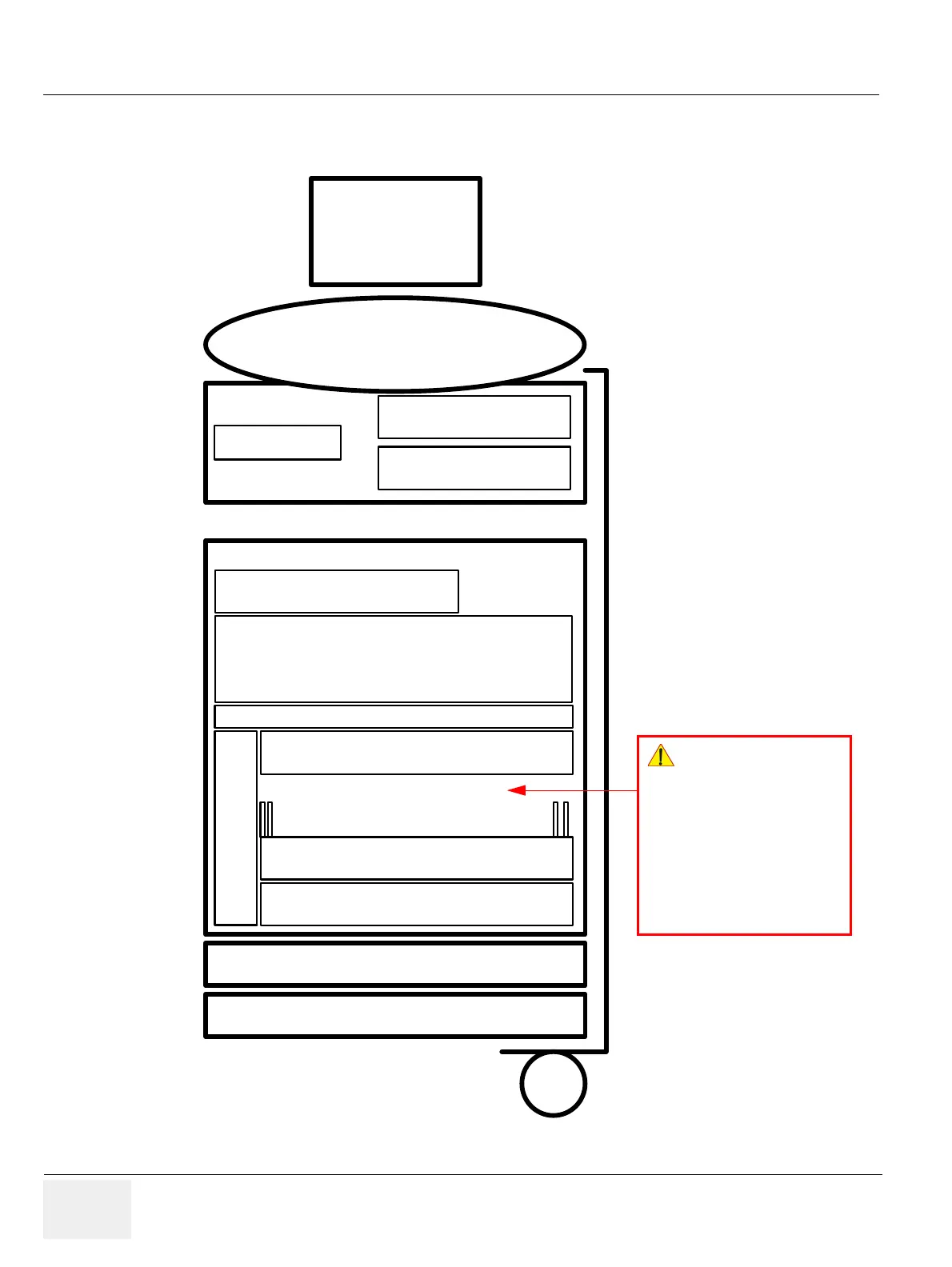
Figure 5-2 Basic Block diagram of Voluson E8 / Voluson E6
Monitor
RTU User-Interface-Module
DVD-Writer
RTT Distribution Board
Top
RTH USB-Hub-Board
RTP Power Supply Secondary
RTN Power Supply Primary
RTB Distribution Board Bottom
PC -Box:
PC-Motherboard with Processor and Memory
ADD2 DVI Card
(at VE6) / Graphic Card (at VE8)
RTV Videoboard
GES 15 I/O Connector Board
RFI RF-Interface
RTK Motherboard
RTF Probe Connector Board
RTM Beamformer Mother Board
16 x RST (Transmitter),
16 x RSR (Receiver),
RSW (CW-Doppler)
..
.
..
.
GEZ Main Board Chassis
RTP5 at VE6
RTP60 at VE8
!! NOTICE:
16 x RST (Transmitter),
8 x RSR (Receiver) at
Voluson E6 (BT09)
12 x RST (Transmitter),
8 x RSR (Receiver) at
Voluson E6 (BT10/12/13)