GE HEALTHCAREDRAFT VOLUSON E8 / VOLUSON E6
D
IRECTION KTD102576, REVISION 7 DRAFT (AUGUST 23, 2012) SERVICE MANUAL
Chapter 5 - Components and Functions (Theory) 5-47
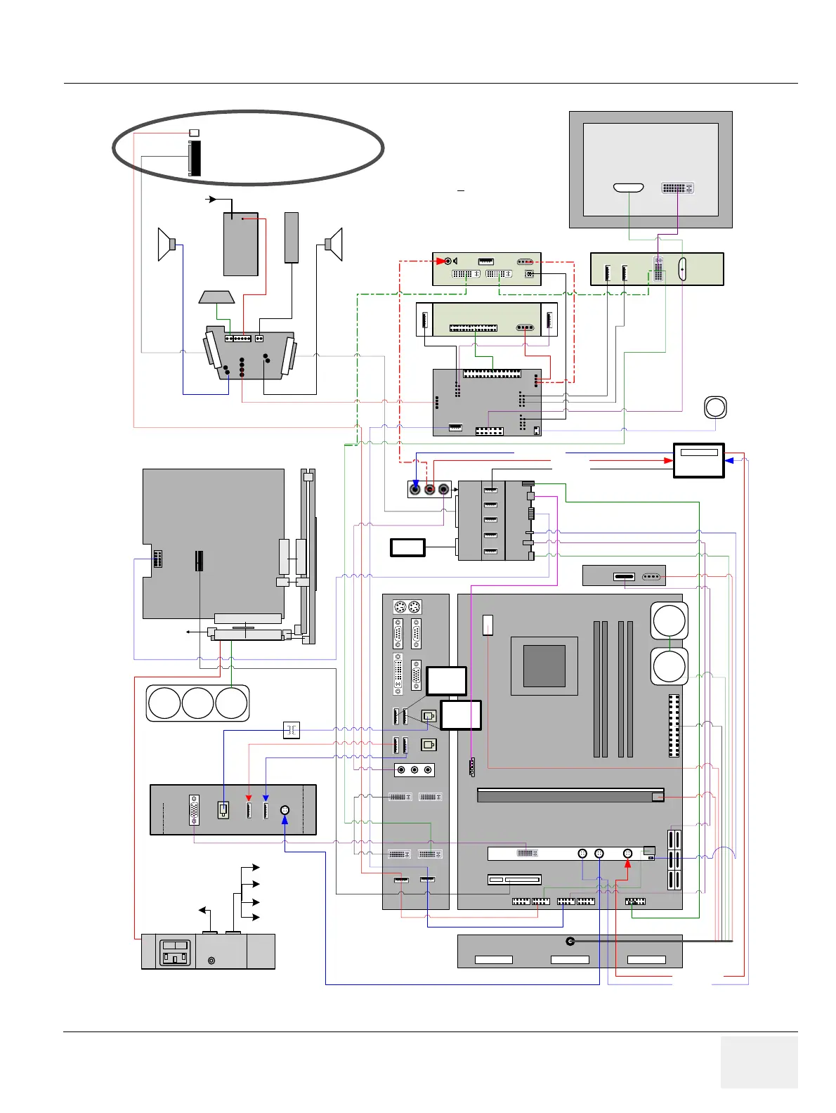
Figure 5-23 Voluson E8 / Voluson E6 (BT12/BT13): Internal I/O - DFI Dual-core PC-Motherboard
PC-Board DFI Dual Core
µP
PWR
RAM
Out
PCI Exp. x 16
Render Graphics board
Fan
Fan
PWR on/off
NC
5V/12V
UI
2.1
2.2
2.3
2.4
U3
U5
U6
RTH
U4
S-ATA
PCI Exp. x4
S - Video
Out1 Out2
In
In
RTV
Out
Out
USB 4
Printer Col
DVD-Rec
USB 3
Printer BW
DVD-Rec
RTP
Conn. 1 Conn. 2 Conn. 3
MicOut In
Top
Bottom
CD Aux
1.3
1.4
1.1
1.2
2.7
2.8
2.5
2.6
RFI
RTK
RTF
RTM
Probe Connectors
To RTP
Conn.1,2,3
REP
GES15
Console back
RTH
USB
USB
USB
USB
PWR
PWR
Video IN Video Out
IN
PWR
DVR
USB
DVD-Writer
IDE
PWR
In Out
PC
RTB
USB
A
C
B
D
E
Console
ECG
RTT
PWR
Monitor
PWR
DVI
RTU User-Interface
Module
Lifter
Speaker
HDD
230V
Brake
Fan
Fan
Fan
From RTN Lift
Fan
LAN isolation
Gel warmer
V-Rec
Aux 1
to right door
Aux 3 V-Rec
or Printer Col.
Aux 2 e.g.
Printer BW
ECG
Video
Audio
Remote
Speaker
From V-Rec. out
To V-Rec. in
USB remote
To V-Rec. in
From V-Rec. out
To Lifter
Aux 4
Not used
I
O
Lift Aux
RTN
Only DVR or DVD-Writer can be installed.
Lines are numbered to see the different
connections. Only (1) or (2) is necessary.
(1) for DVD-Writer
(2) for DVR
(1)
(1)
(1)
(1)
(2)
(2) (2)
(2)