GE HEALTHCARERAFT VOLUSON E8 / VOLUSON E6
D
IRECTION KTD102576, REVISION 7 DRAFT (AUGUST 23, 2012) SERVICE MANUAL
5-48 Section 5-6 - Top Console (User Interface)
Section 5-6
Top Console (User Interface)
The Voluson E8 / Voluson E6 Control Panel (User Interface) consists of the following electronic
subassemblies and/or functional components:
• Display/Touch screen module:
- VGA display – 640x480 pixels
- Integrated USB to VGA converter with USB2.0 High Speed Interface
- Resistive 5 wire analog touch screen
• Console module:
- Micro controller C8032
- 4 port USB 2.0 Hub controller
- Slide pots TGC with zero raster position
- Rotary Encoders with integrated push buttons
- USB Trackball (2”) with dedicated buttons to emulate standard three button mouse
- USB standard alphanumeric keyboard
- USB extended keyboard with controller
- LED Indicators with wide range dimming
• DC/DC Converter:
- Converts 12VDC input voltage to 5VDC and 3.3VDC output voltage for supplying
User Interface components
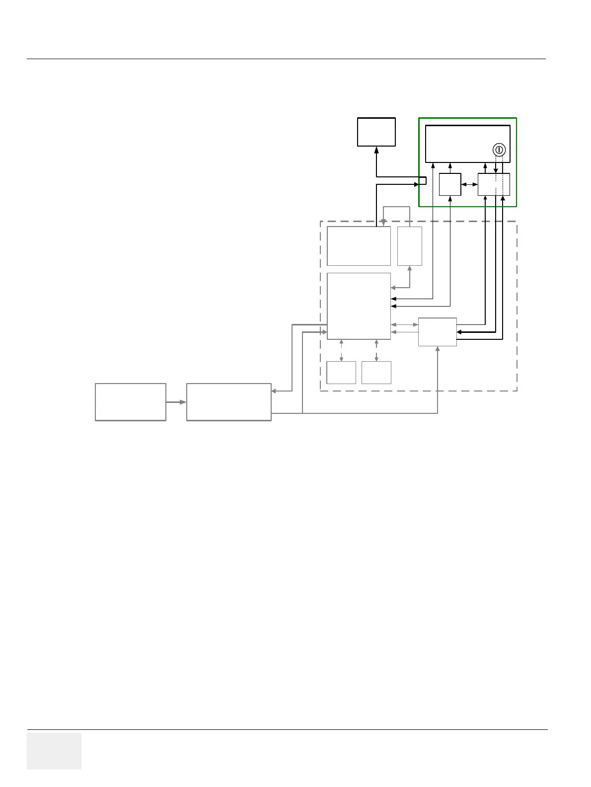
Figure 5-24 Front End Processor - Block diagram
RTP Secondary
Power Supply
Console
(User Interface)
PC
Motherboard
RTV
- Video Management
(Legacy Analog Video I/O
and digital VCR, MPEG-2)
ADD2- Card
or
Graphic - Card
HDD
Optional
Device
Serial ATA
PCI-Expr.
RTB
Distribution
Board
RTN Primary
Power Supply
Monitor
Serial ATA
RTH
RTT
DVI-out
DVI-cable
BackEnd
ON/OFF
5V STB (Standby)
5V STB (Standby)
5V STB (Standby)
PS_0N (0..on, 1..off)
ON/OFF
ON/OFF
USB Hub Top
USB UI