GE HEALTHCARERAFT VOLUSON E8 / VOLUSON E6
D
IRECTION KTD102576, REVISION 7 DRAFT (AUGUST 23, 2012) SERVICE MANUAL
5-64 Section 5-12 - Air Flow Control
Section 5-12
Air Flow Control
5-12-1 Air Flow Distribution
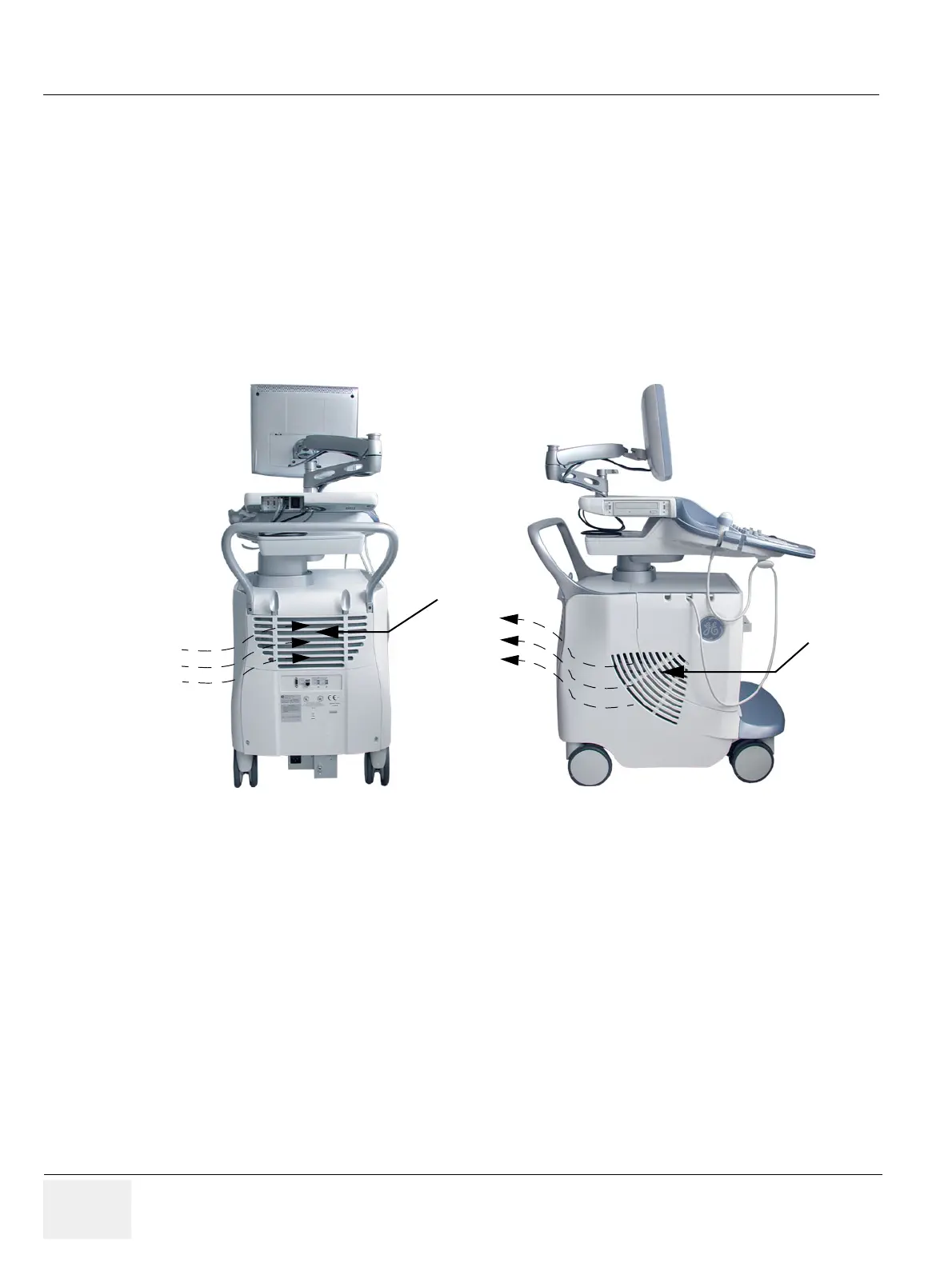
Through the filter grid on the back of the system (Main Air Inlet), air flow into the Voluson E8 / Voluson
E6 scanner.
• Air holes in the RTP secondary power supply allow the air to pass through; the 3 fans (between RTP
and Beamformer) suck in the air and spread it through the beamformer and around the RFI board.
• By means of the 2 Backend fans, air is blown through the GEB-box (along its internal components
and the PC- Motherboard).
The warm air exits the scanner through holes in the left side panel (Main Air Outlet).
Figure 5-37 Main Air Inlet/Outlet at Voluson E8 / Voluson E6
Main Air
Outlet
Main Air
Inlet
(Filter grid)