GE HEALTHCARERAFT VOLUSON E8 / VOLUSON E6
D
IRECTION KTD102576, REVISION 7 DRAFT (AUGUST 23, 2012) SERVICE MANUAL
8-32 Section 8-17 - Replacing optional Peripherals / How to mount Peripherals at a later date
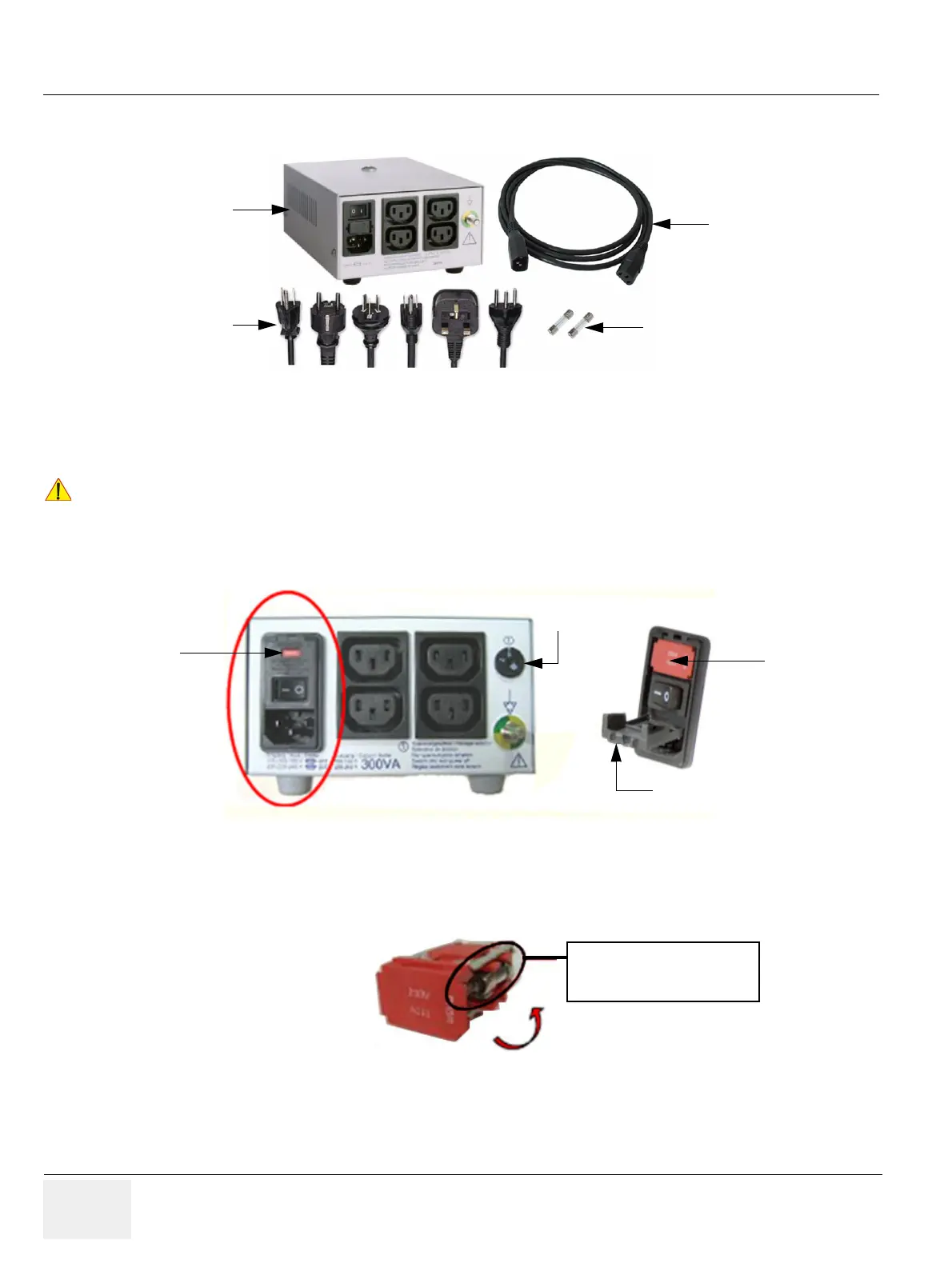
8-17-4-4 Preparing the Isolation Transformer
1.) Before using the Isolation Transformer you must check the input voltage settings to meet the ratings
of the line power available in your location or country.
2.) For changing the input voltage, open the fuse protection at the power inlet block with a small
screwdriver and remove the fuse holder.
3.) By turning the fuse holder you can select 115V or 230V.
Consider that changing the input voltage also requires to change the fuses!
Figure 8-40 Isolation Transformer kit for 19” LCD Secondary Monitor
!! NOTICE:
The wrong fuses and position of the voltage output selector may cause major damage on connected
peripherals.
Figure 8-41 changing input voltage
Figure 8-42 input voltage setting
Isolation Transformer
Monitor Power cable
Fuses (2AT, 4AT)
Power Cord set
fuse holder
fuse protection
voltage
(e.g. 230V)
is shown in
this window
voltage output
selector
115V (100-130V) -> 4AT
230V (220-240V) -> 2AT